Last year burglaries were happening in my rural area and even in my tiny village, where I grew up. Unfortunately burglary is now a common occurence for the last few years in my area where I live at the moment. Burglars also broke into the garage of my family home and stole the old motorbike of my brother:
 It's a real shame. A short while later another burglary happened during the night next to my home. My mother, who slept with her window open and couldn't sleep so well since the first accident, heard the burglars during that night. We called the police and it took them between 45 and 60 minutes to arrive. They came from the Police Station in Straußberg, which is pretty far away from my home. Now you see the dilemma. The new counter measurement against them is to let the street lights burn the whole night, which is of course super energy efficient.... Additionally my father let me know, that people want to create a civil defense against the burglars. They asked my father, if he would like to patrol at night, because he is a pensioner. Both things are unnecessary in the age of IoT.
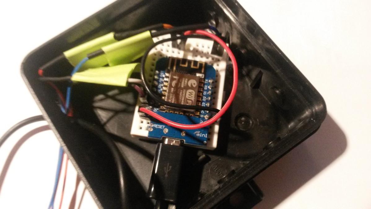
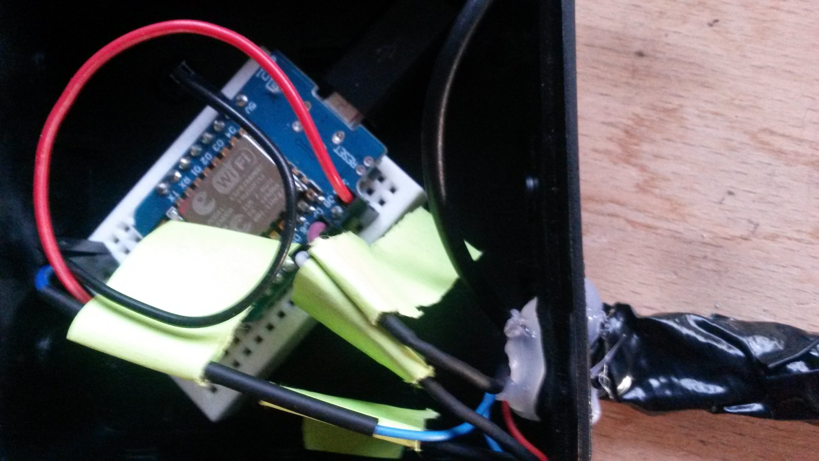
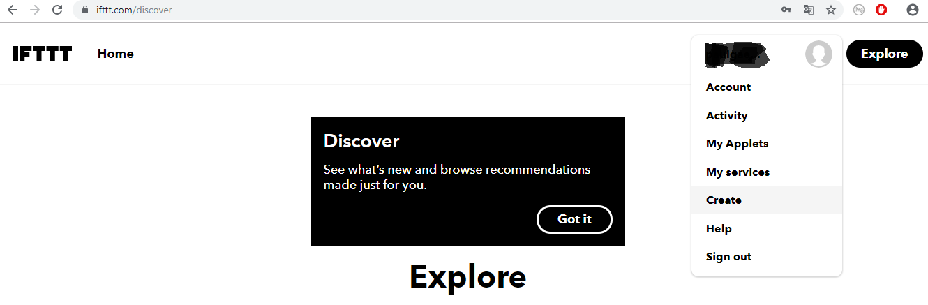
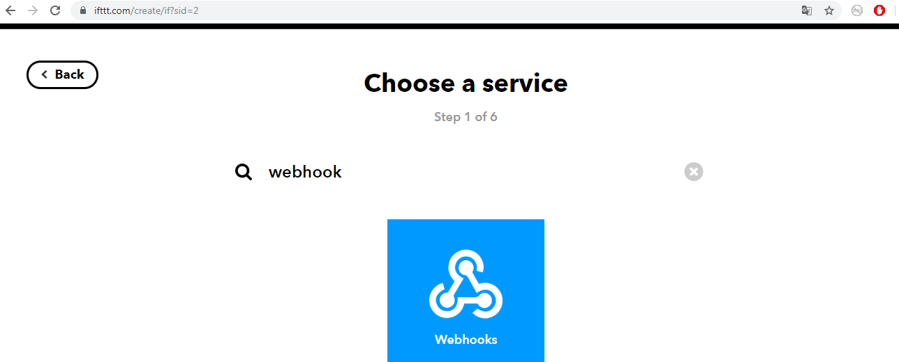
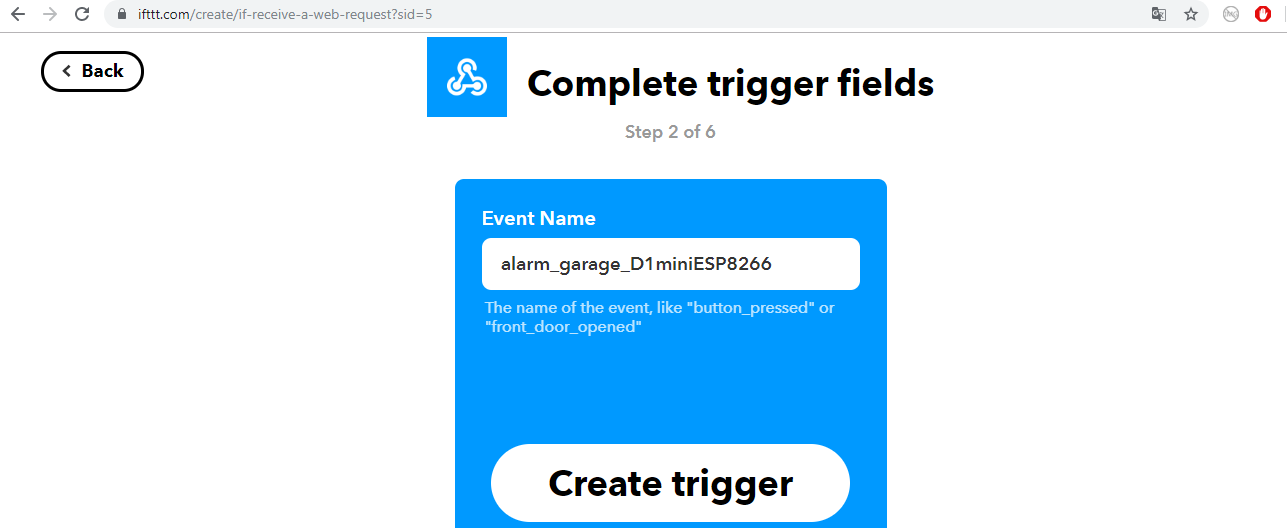
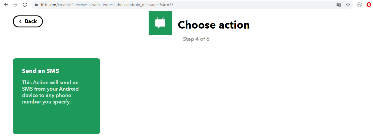
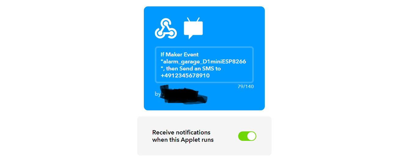
 The goal of my project was to create a cheap home alarm system using a microcontroller with a wifi module, a distance measurement sensor and a webhook notification (SMS to my smartphone, when our garage door gets opened). Not an overly complex project, but a fun one.
I didn't want to include something in my project, which creates noise (for instance a sirene), because there is still the chance that the police can appear in a timely manner. In the case the closest police patrol is too far away, we can still use the megaphone I've bought for my mother to scare the burglars away. :P
The project is relatively cheap. Most likely most of the components I've used are lying around in your own Maker Lab already. The components section shows you all the items and tools, which were mandatory for me to complete the project. The components section shows you also were I've bought all my components and tools originally. The following components have to be purchased most likely:
- SYB-170 breadboard (AliExpress)
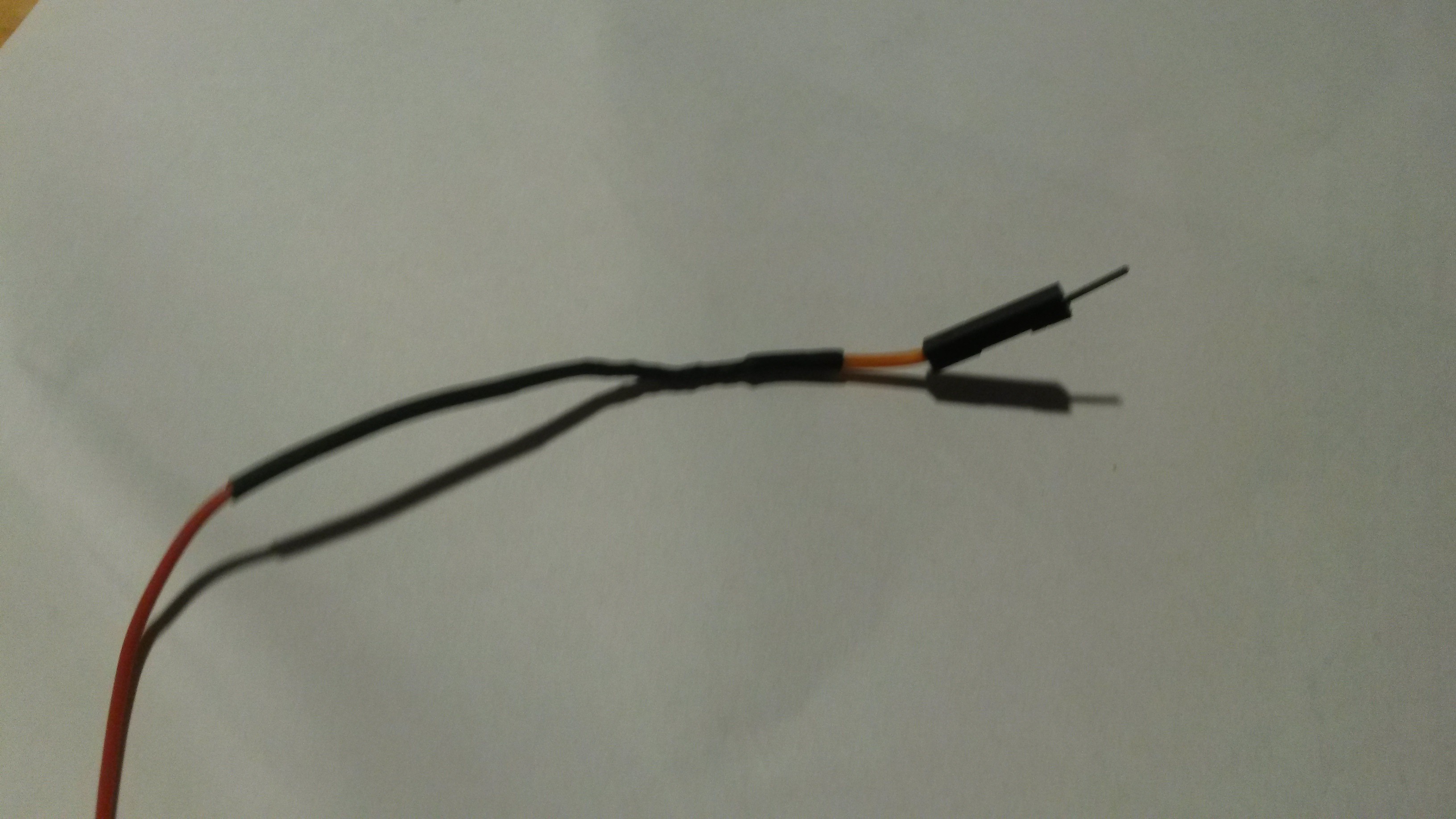
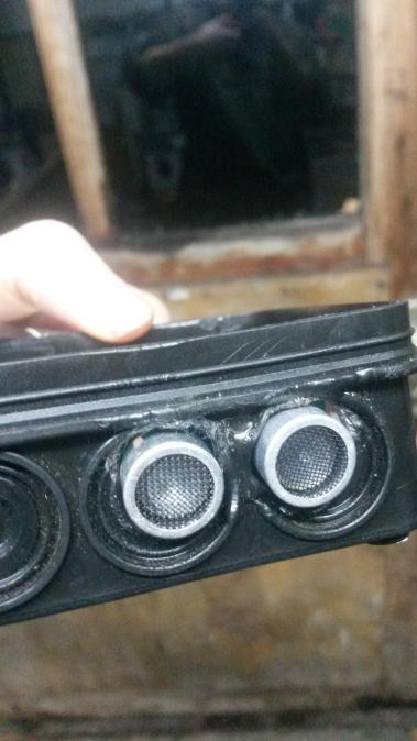
- RCW 0001 Micro Ultrasonic sensor (AliExpress)
- D1 Mini ESP8266 (AliExpress)
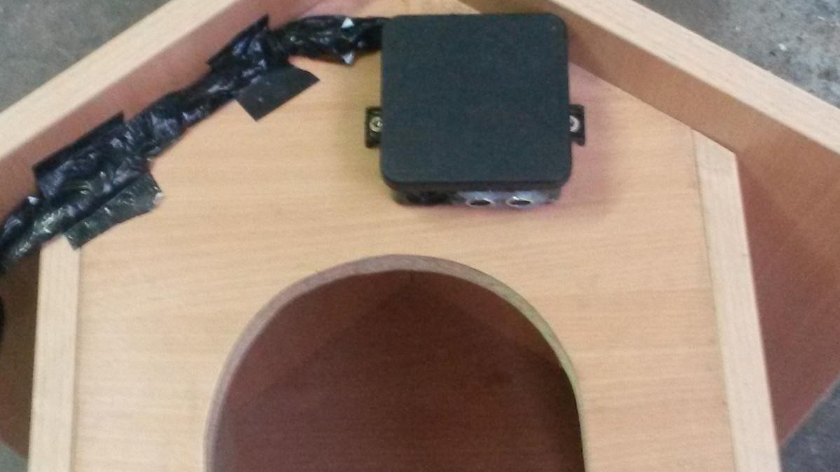
- 2x Distribution box (Ebay Seller in Germany)
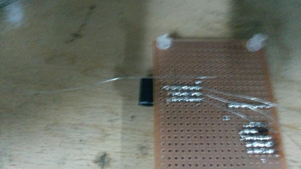
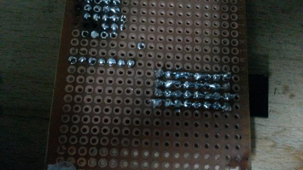
- PCB 5x7 cm (Ebay Seller in Germany)
- Wall socket battery charger 5V (Conrad)
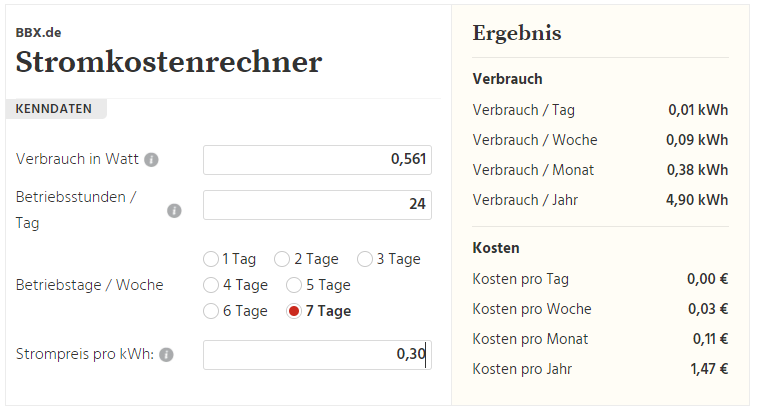
The project costs are approximately 18 Euro, if you don't include the delivery costs.

 Sam Griffen
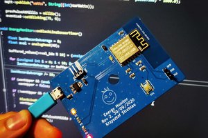
 h4rdc0der
 Dan
Dan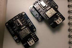
 AKA
AKA