0%
0%
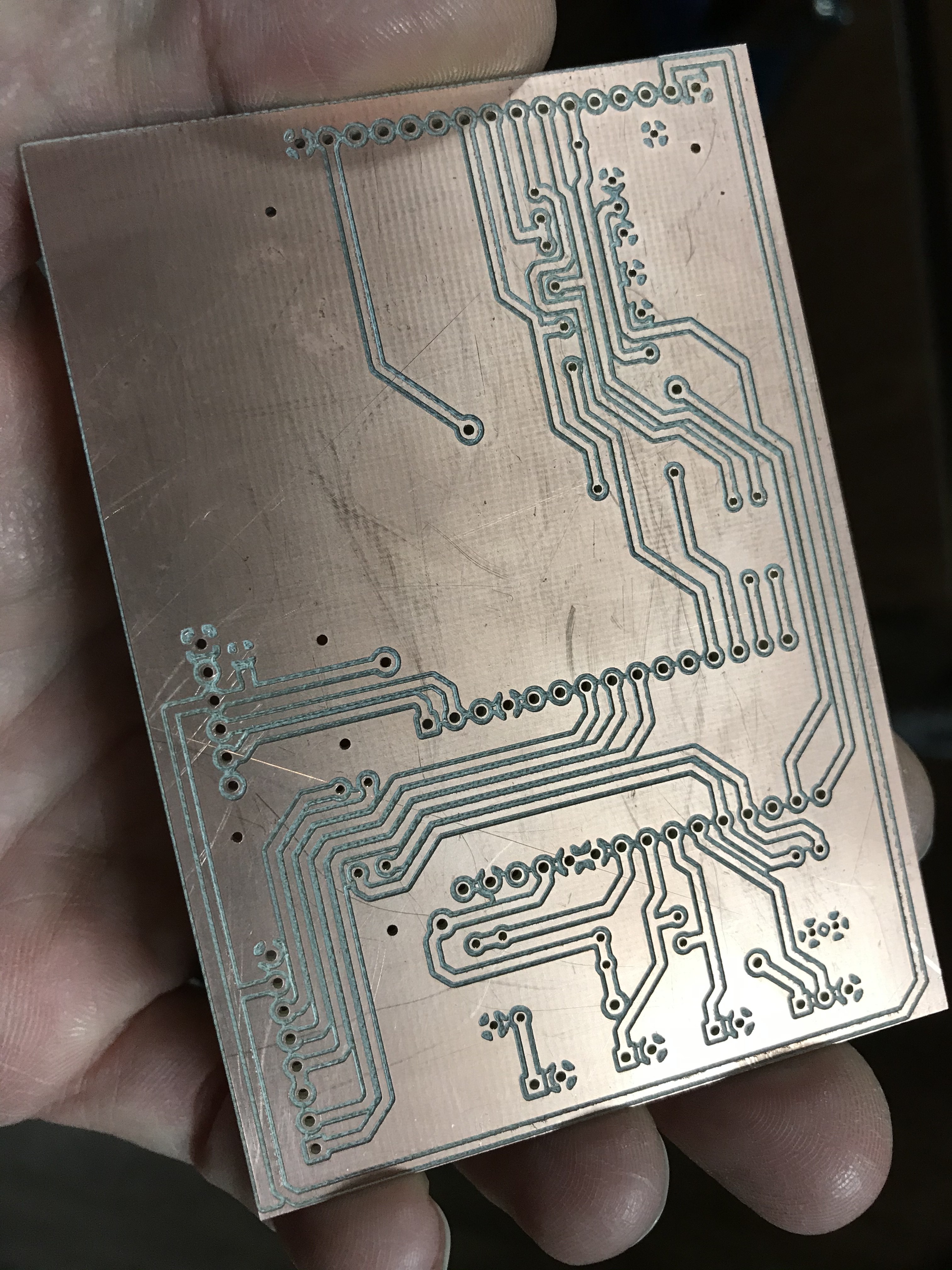
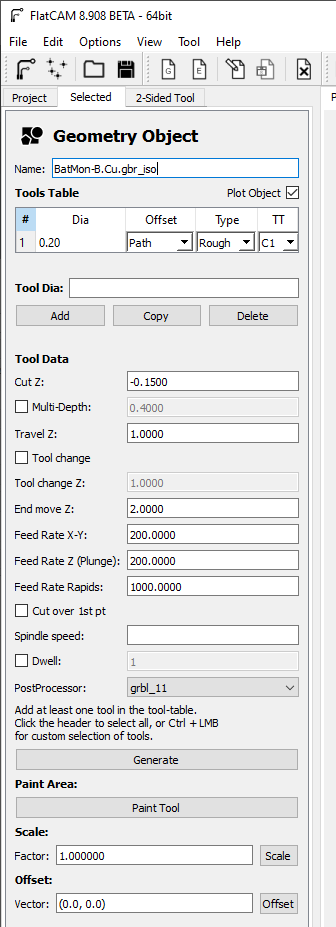
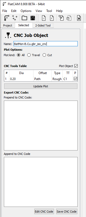
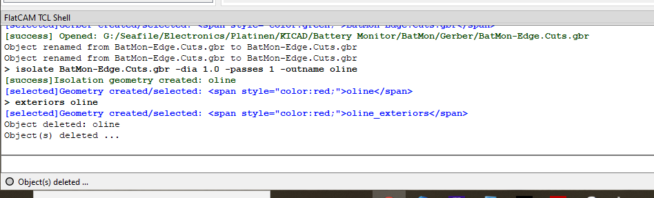
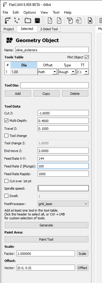
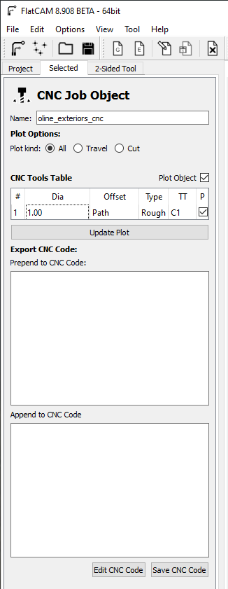
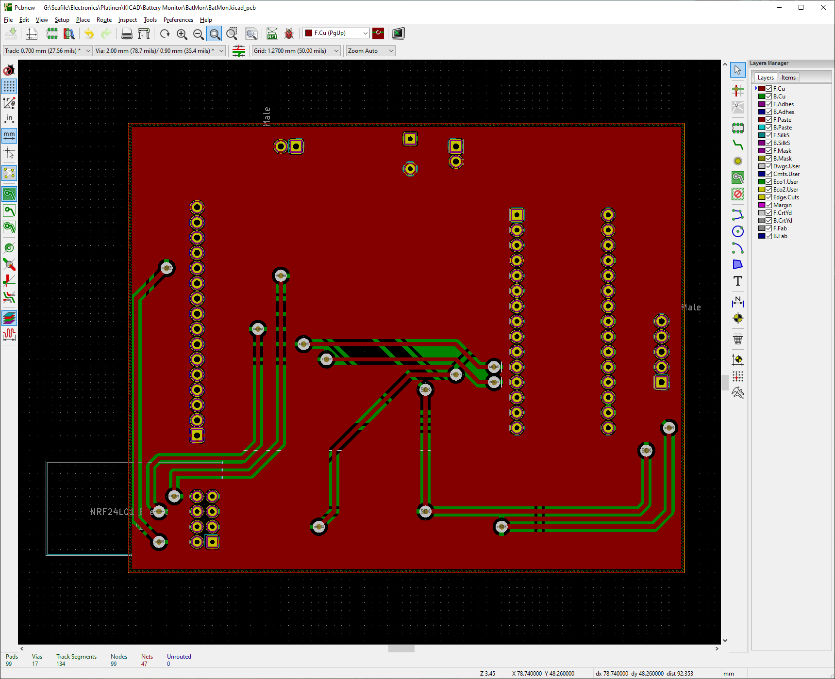
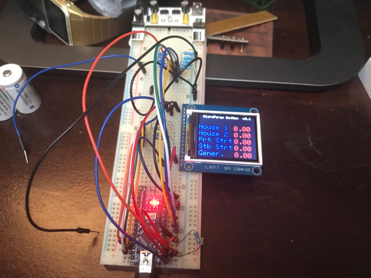
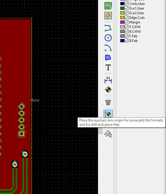
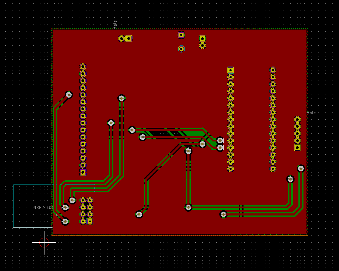
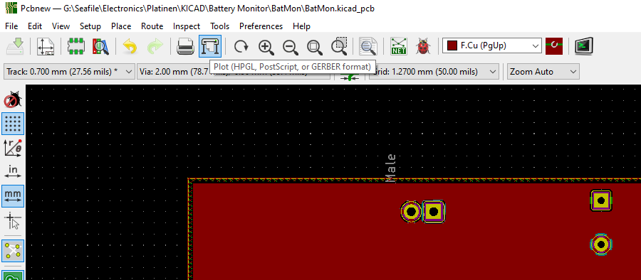
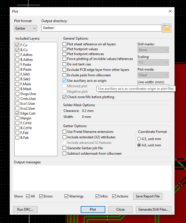
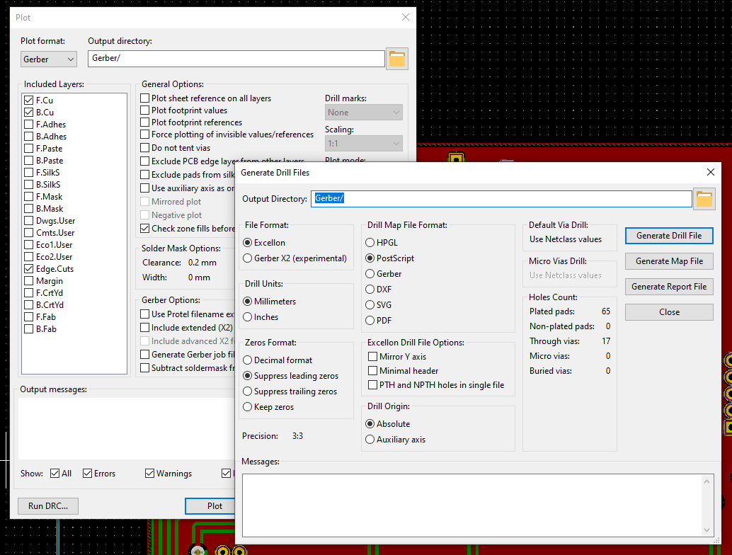
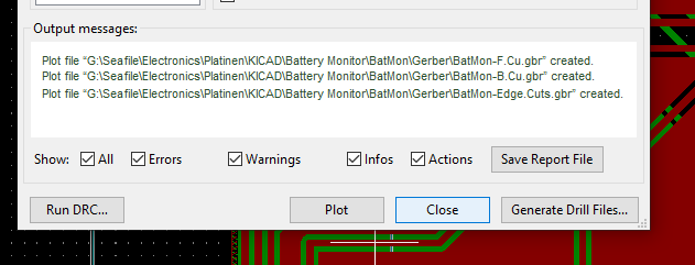
From KiCAD Design to Milled PCB in FlatCam
Having a finished design comes the prototyping fabrication. This is a step by step tutorial.
 Timo Birnschein
Become a Hackaday.io member
Already have an account? Log in.
Just one more thing
To make the experience fit your profile, pick a username and tell us what interests you.
Pick an awesome username
hackaday.io/
Your profile's URL: hackaday.io/username. Max 25 alphanumeric characters.
Pick a few interests
Projects that share your interests
People that share your interests


 adellelin
 fl@C@
fl@C@
 Josh
Josh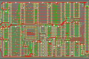
 Keith
Keith
just wondering what router you use?
and any comments on its suitability/pitfalls