 Timo Birnschein
To change the export precision, use the command
set_sys cncjob_coordinate_format "x%.3f y%.3f"
before any other operation
Top Side Milling:
====================
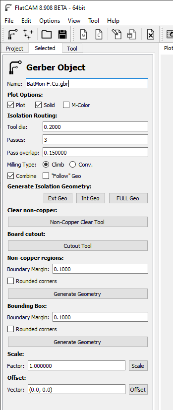
Load the Gerber file.
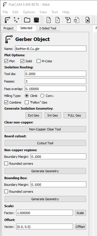
Double click on the top Gerber and generate the geometry using the following parameters:
Tool dia: 0.2
Width (# passes): 3
Pass Overlap: 0.15
Combine Passes: checked
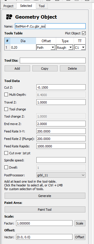
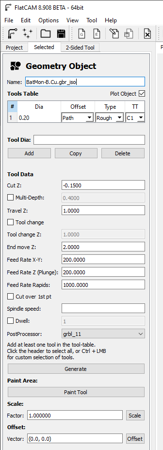
Back to the project, select the generated isolation file and set the following parameters to generate the CNC path:
Cut Z: -0.15 -- Proper Z-leveling is mandatory
Travel Z: 1.0
Feed Rate X-Y: 200
Feed Rate Z (Plunge): 200
Tool Dia: 0.2
Multi-Depth: NOT checked
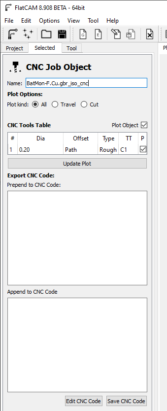
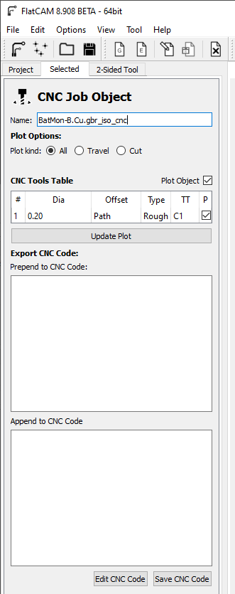
Back in the project, double click on the selected CNC file, check your tool diameter again and hit Export G-Code
Top Side Drilling:
====================
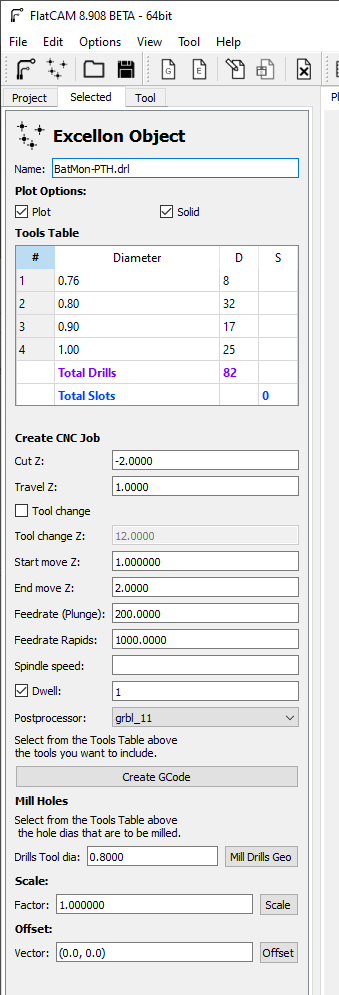
Load the Excellon drill file.
Double click on the drill file, select the tool you want to use from the list and generate the geometry using the following parameters:
Cut Z: -2
Travel Z: 1.0
Feed Rate: 200
Tool Change: NOT checked
Back to the project, select the generated CNC file, check the tool diameter, update the plot and then export the G-Code.
Bottom Side Milling:
====================
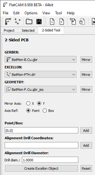
Load the Gerber file and go to the double sided tool. Select the bottom Gerber file and hit Mirror Object with the same parameters as used for the outline.
Mirror Axis: Y
Axis Location: Point
Point/Box: (0,0)
Back to the project, double click on the bottom Gerber and generate the geometry using the following parameters:
Tool dia: 0.2
Width (# passes): 3
Pass Overlap: 0.15
Combine Passes: checked
Back to the project, select the generated isolation file and set the following parameters to generate the CNC path:
Cut Z: -0.15 -- Proper Z-leveling is mandatory.
Travel Z: 1.0
Feed Rate X-Y: 200
Feed Rate Z (Plunge): 200
Tool Dia: 0.2
Multi-Depth: NOT checked
Back in the project, double click on the selected CNC file, check your tool diameter again and hit Export G-Code
Outline milling:
================
I mill the outlines last. They need to be mirrored using the tools for double sided PCB and the following parameters:
Mirror Axis: Y
Axis Location: Point
Point/Box: (0,0)
Leave the rest and hit Mirror Object
Back in the selected tab, select the correct outline file and use the command line tool
isolate OpenRemote-Edge.Cuts.gbr -dia 1.0 -passes 1 -outname oline
To generate the custom outlines of the board.
Then use
exteriors oline
To generate a copy of the previously generated outlines but only the exterior outlines.
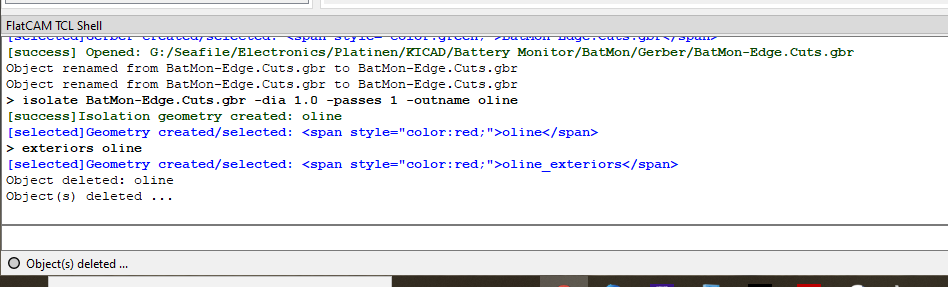
Back in the project overview, the olines can now be deleted and only the olines_exteriors remain. That file will now be used to generate the CNC cutting file.
Select the oline_exteriors file to process the the CNC job with the following parameters:
Cut Z: -1.6
Travel Z: 1.0
Feed Rate: 144
Tool Dia: 1.0
Multi-Depth: checked
Depth/pass: 0.4
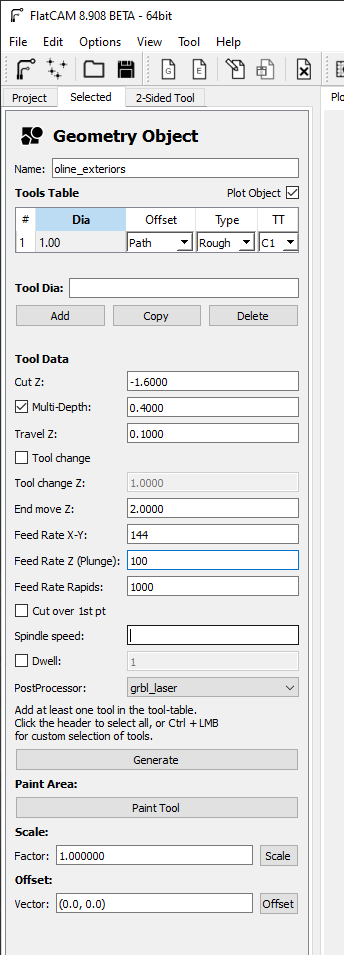
This generates a nice CNC path around the edges of the PCB with a 1mm endmill and multiple passes per full Z.
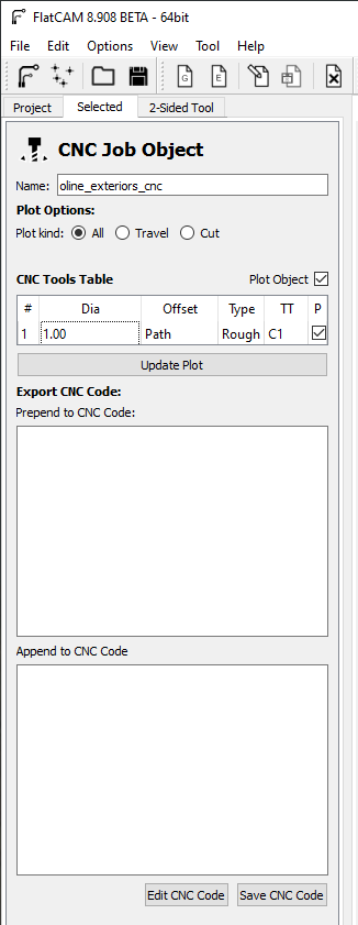
Back in the project, double click on the selected CNC file, check your tool diameter again and hit Export G-Code
Discussions
Become a Hackaday.io Member
Create an account to leave a comment. Already have an account? Log In.