 Just4Fun
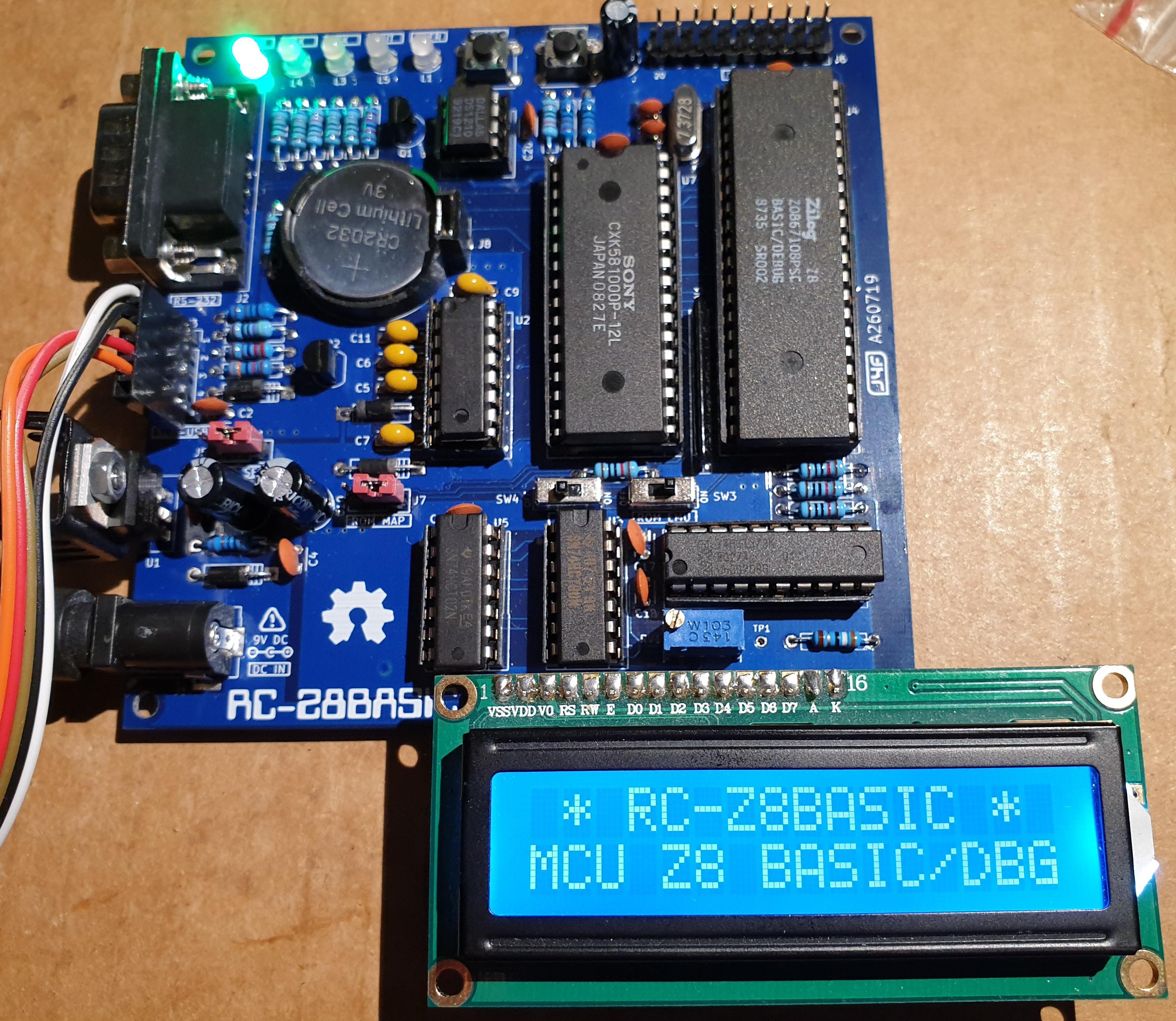
* * HARDWARE OVERVIEW * *
NOTE: Before use this board it is highly recommended to read the Z8671 Basic/Debug Software Manual to understand how this MCU works together with the provided BASIC/DEBUG environment.
The specs of the RC-Z8BASIC are:
128KB SRAM with battery backup, RS-232 port, serial-USB adapter port, GPIO port, LCD (1602 or 2004) port, User led and key, on-board power supply, ROM emulation mode to enable the "Auto execution at power-up/reset" feature, can be powered from USB or on-board power supply.
Because this board use only a SRAM with a backup battery for data retention, you don't need any legacy EPROM programmer.

It is possible select a ROM emulation mode to use half the SRAM address space as ROM. When the ROM emulation is active it is possible use the "auto execution at power-up/reset" feature of the ROM Basic inside this MCU.
Two different ROM emulation mode are possible. The selection is done with the J7 jumper.
The first time you power on this board (or after changing the SRAM backup battery) you need to do the "INIT PROCEDURE" to set the wanted baud rate (that is stored inside the SRAM).
The RC-Z8BASIC has a RS232 serial port, but there is also a "transparent" serial-USB connector to use a common serial-USB adapter.
It is possible plug a common LCD module (1602 or 2004) into the LCD (J4) connector, but you have to write the low level driver yourself (but I've already written a demo Basic driver for it...). Note that the LCD connector shares some GPIO of the GPIO (J6) port.
There is also an USER led and a USER key (sharing two GPIO with the J6 GPIO connector too).
You can power the board from the on-board power supply or from USB using a common serial-USB adapter. The selection is made with a jumper (J5). The HW can manage the mixed powering situations when you power the board with the on-board PS (Power Supply) and are using the serial-USB adapter for the serial data link (USB adapter not powered from the host USB while the board is powered, and vice-versa) so you don't need to have care of this detail.
* * SRAM * *
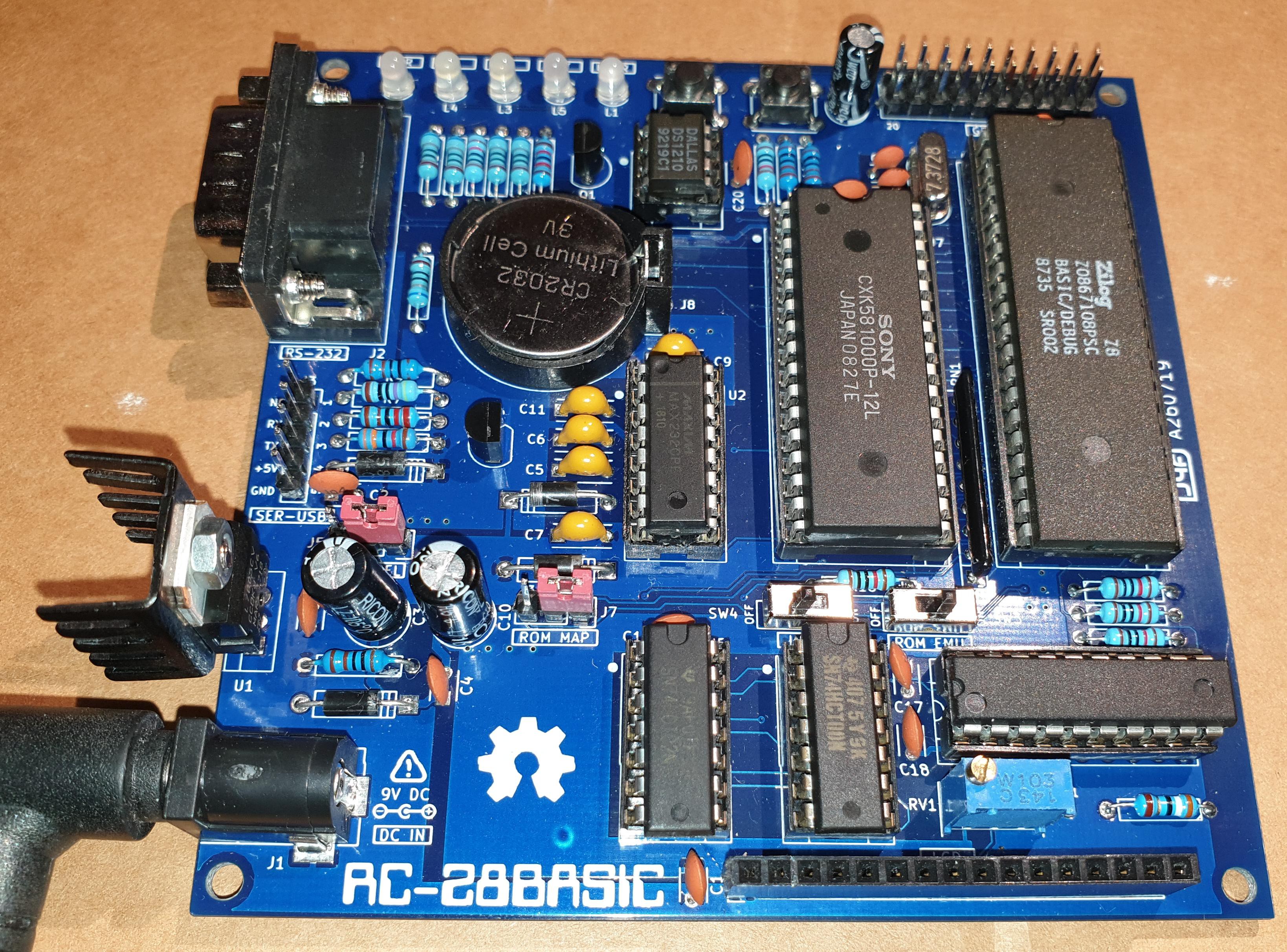
I've used a TC551001 just because is cheap on Ebay. You can use any speed variant (70/85/100ns) or any equivalent 128KB SRAM chip. In the photos I've used another SRAM chip with a speed grade of 120ns without any problem.
* * J5 AND J7 JUMPERS SETTING * *

Please note that the total 128K bytes address space is managed by the DM signal (pin 29 of the Z8 BASIC/DEBUG MCU) that selects one of the two 64K bytes pages available, while the "normal" Z8 address space used for the program and data is 64K bytes large. The "second" Z8 64K bytes page can be used when it is enabled the DM function (see the manual) and can be accessed using a couple of assembler instructions.
* * INIT PROCEDURE * *
@%FFFD = 1
* * SW3 (ROM EMU) SWITCH * *
* * BASIC DEMO EXAMPLES * *
In the Files section there is a zip file (Examples.zip) with a couple of Basic demo programs to see the RC-Z8BASIC in action.
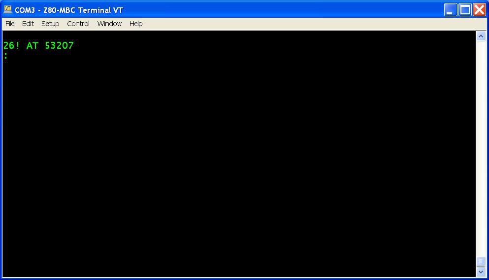
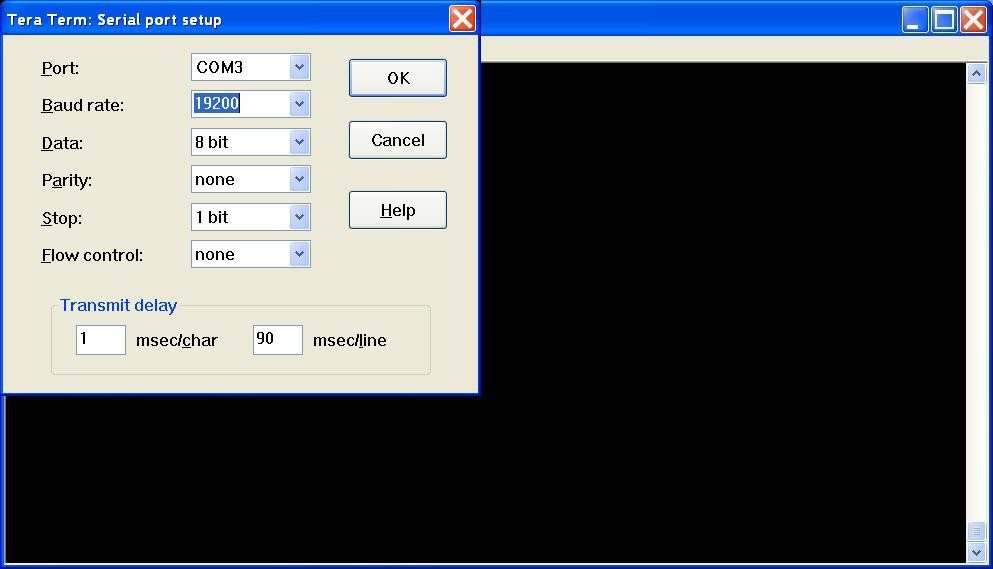
To send the files to the RC-Z8BASIC it is needed a terminal emulator program like Tera Term. Remember to set the speed to 19200, a transmit delay between characters of 1ms and a delay of about 90ms at new line (see the following screenshot):
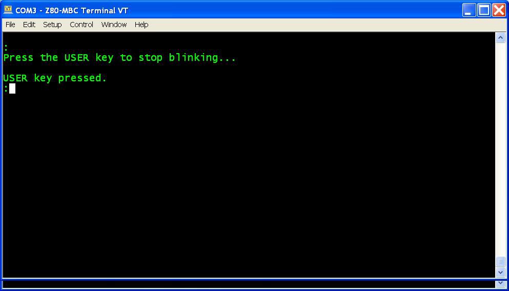
The UserLedKey.txt is a demo using the User led and key.
The LCD.txt demo program requires a 1602 or 2004 LCD module fitted in the J4 (LCD) connector. To adjust the LCD module contrast you must use the RV1 trimmer. There is also a test point (TP1): with the LCD module inserted you must set the RV1 trimmer to read about 1.1V with a DVM, then you can do a fine tuning while the LCD.txt demo is running.
* * AUTO EXECUTION AT POWER-UP/RESET * *
On power-on/reset, Z8 Basic/Debug sizes RAM memory and checks
for an auto start-up program (see the manual).
Automatic start-up allows a program stored in ROM to be executed on reset without operator intervention. Automatic execution occurs on power-up/reset when the program:
- is stored in ROM;
- begins at 0x1020;
- begins with a line number between 1 and 254 inclusive.
When Z8 sizes the RAM it stores the first available location to store a program in the R8-R9 registers pair.
So when the SW3 switch (ROM EMU) is in the OFF position (all RAM) it stores 0x0800 inside R8-R9, while if SW3 is in the ON position and J7 (ROM MAP) "jumps" pin 2 and 1, it stores 0x8000 inside R8-R9.
So an easy way to store a program starting from 0x1020 is to set SW3 in the OFF position and tweak the R8-R9 registers pair writing the wanted starting address.
At this point it is possible load the program using a terminal emulator, and then set SW3 to the ON position enabling the ROM emulation, so at the next reset/power-up the program will be automatically executed.
So the procedure to load a program and execute it automatically at power-up/reset is:
1. Check that J7 is in the default setting (pin 1 and 2 jumped) and SW3 is OFF, then press the RES key (just to be sure);
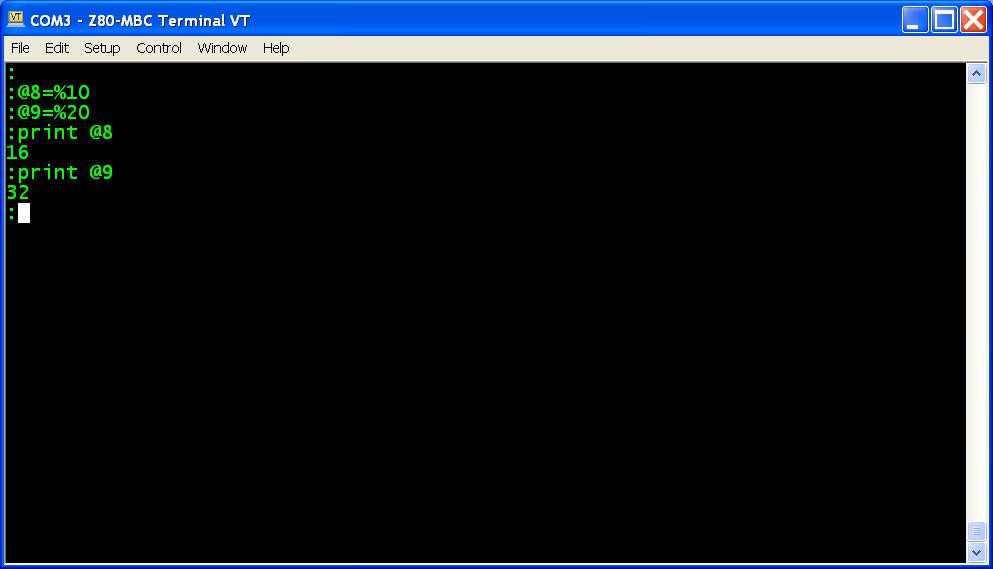
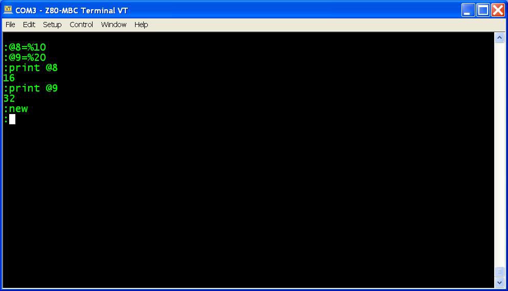
2. Using a terminal emulator give the commands @8=%10 and @9=%20 (optionally re-read both registers with the PRINT command that will show them in 10 base:)
3. Give the command NEW to erase a previous program starting at 0x1020:
4. Load the wanted program using a terminal emulator (using the send file command or as it is called on your emulator);
5. Give the LIST command just for a "visual check";
6. Set SW3 to ON and press the RES key. Your program should start ! (the same when powering on the board).
All done!
* * WHERE TO GET A PCB * *
I've prepared an "easy" link to get a small lot (5 pcs minimum) of PCB. The link is this one.