 Timo Birnschein
After more than one year, I finally revisited this project to finish it and install it on my boat. I admit, every time I saw this unfinished and somewhat too simple of a project it was a burden on my mind. First of all, this seemingly simple system has the ability to safe my life when shit hits the fan undesired events occur in unstructured environments, and second, it can be extremely valuable to evaluate the health of my battery and charging system.
After all, I have a 500Ah house bank, two bad ass AGM starter batteries for my two 8 liter Diesel engines and one normal acid based starter battery for my 8Kw generator. You really don't want to loose or damage them if not absolutely unavoidable.
So to get back into it, I decided to start designing an enclosure in Solidworks. An interesting task if it's not entirely clear what the dimensions of the PCB are. Luckily, KICAD offers a STEP export which allowed my to get all the important dimensions straight from the PCB layout tool.
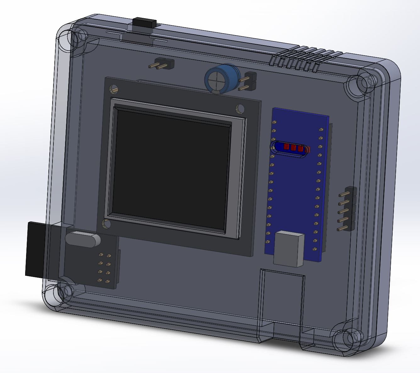
The rest was a matter of making things fit to the PCB design. It's not my most beautiful PCB but it's functional and reasonably accessible. I'm definitely still learning this, as some of the connectors are ill-placed and required some creative soldering to make work. That's especially true for the most important connector: The batteries.
After designing and printing the enclosure I was very happy to see that everything fit together nicely without modifications.
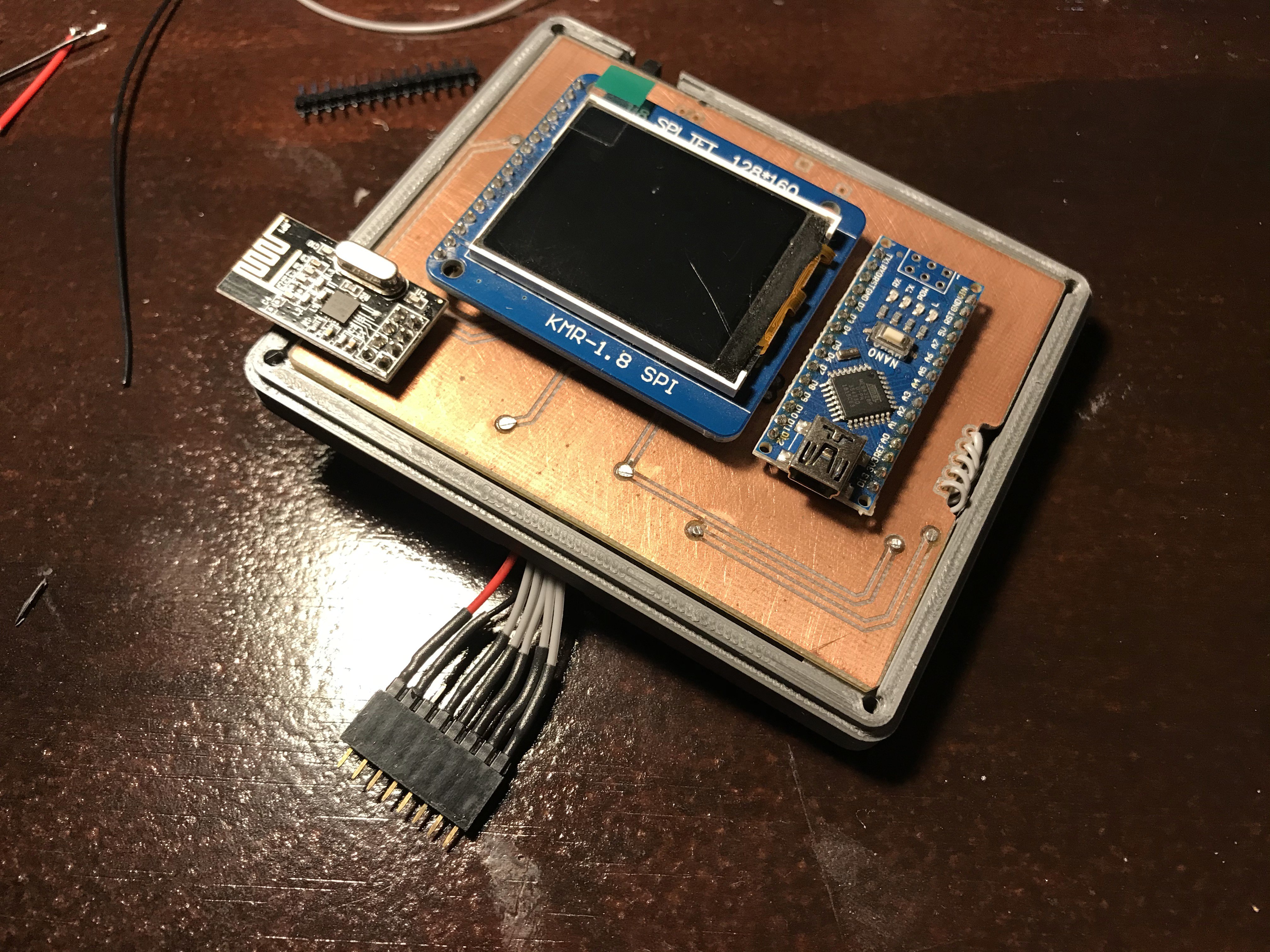
I also finally soldered the RF module to the PCB giving me some future expandability once I get bored and actually install RF24Network on my Board Computer.
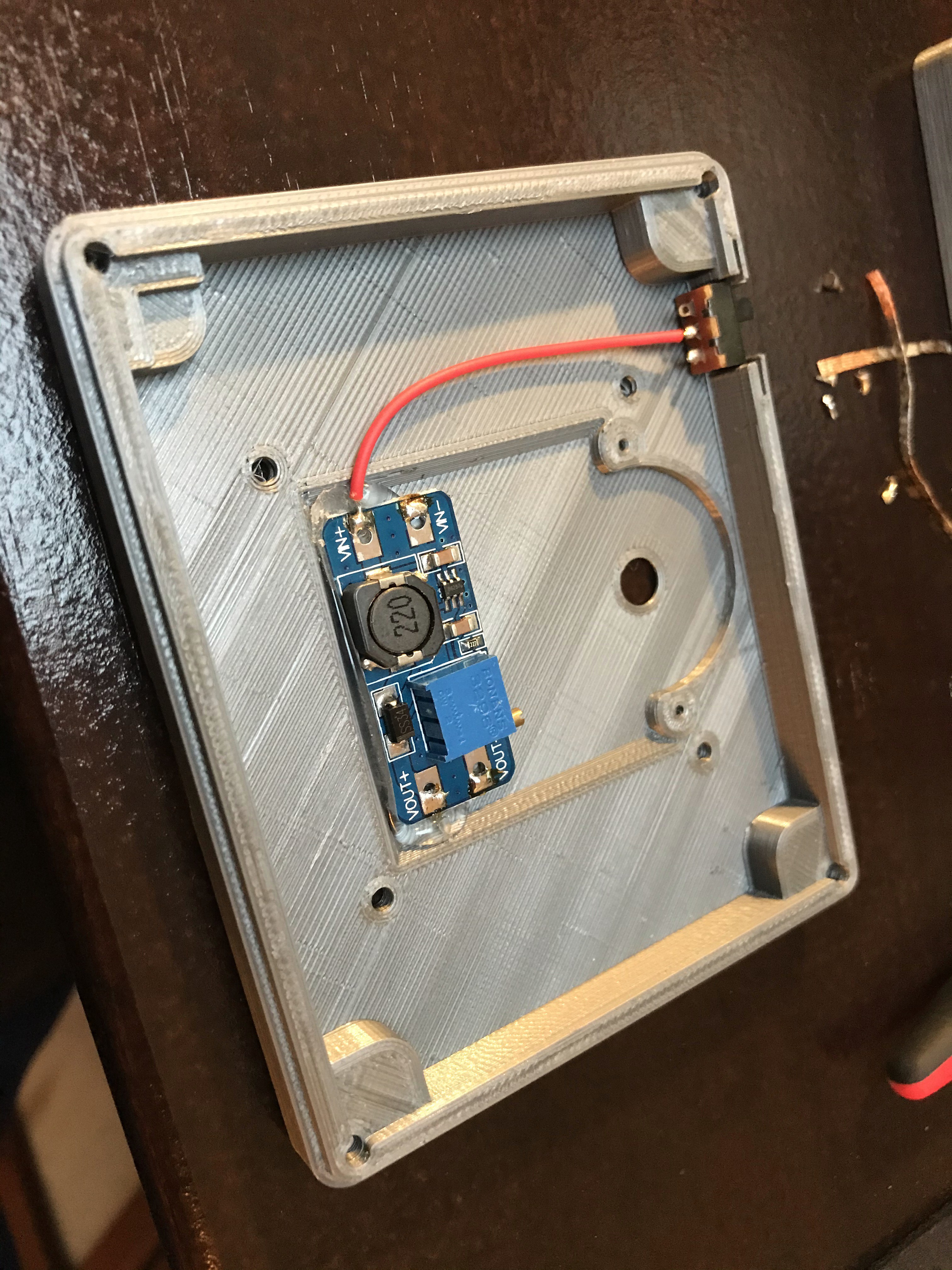
Inside are two major components, one rather loud piezo beeper in case a battery runs into an under-voltage situation and a a power converter to convert unregulated 12V into regulated 5V. I was naive and used a cheap step-up converter only to realize that it spits out its input voltage. I'm VERY glad I checked before I soldered everything together. To be clear, this doesn't work. Just posting this picture for completion:
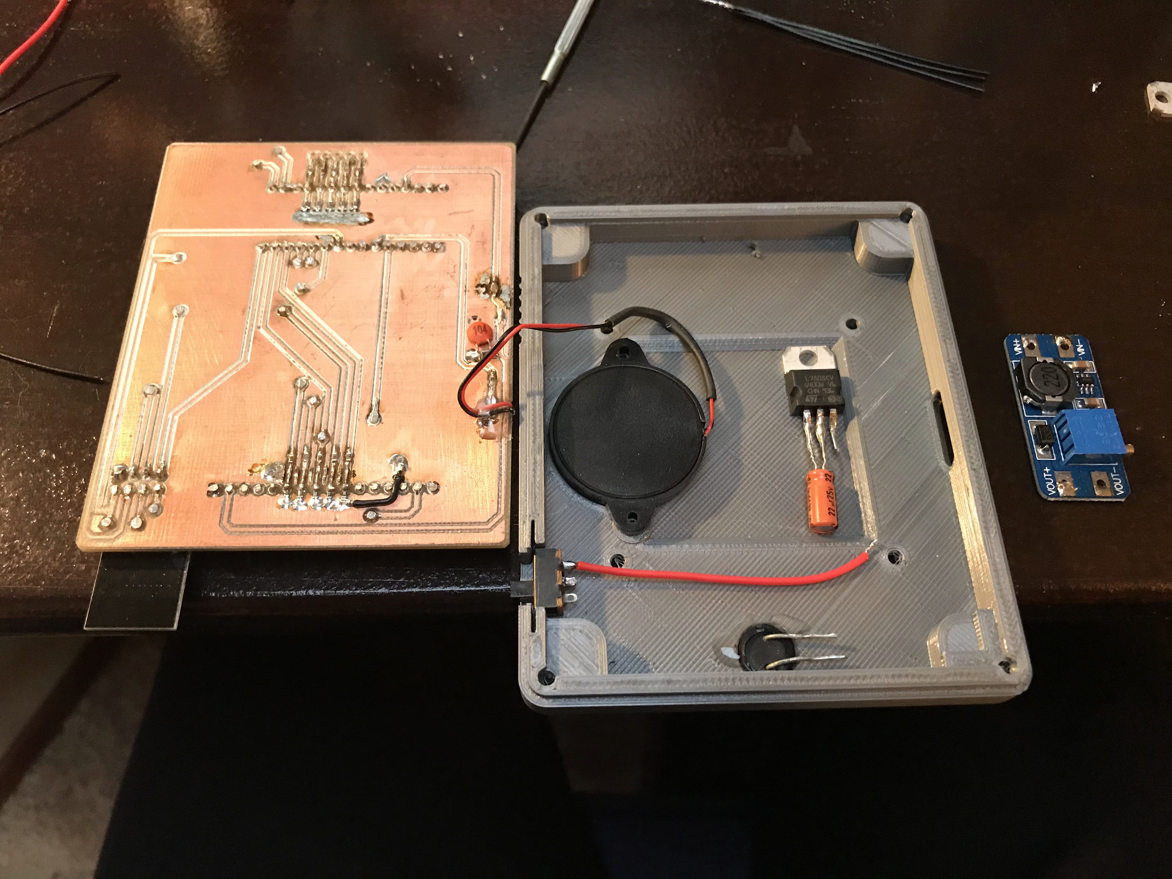
Instead, I searched my trusty parts bin and found an unused 7805 and matching capacitors. This will provide 5V to the module even in bad conditions:
I installed the beeper in a pocket designed for it. Usually, I use hot glue or screws to fix this stuff in place but something drove me to use CA glue instead. That was a terrible idea! So far without consequences but keep in mind that the adhesion of hot glue can be very easily neutralized using a drop of isopropanol! That's not at all the case with CA glue. Removing these components for whatever reason will be a pain.
After everything was put together, I finally realized that none of my strategies for connecting the actual batteries to this monitoring module won't work. I therefore had to resolve to the worst possible method I could think of and use ... pin-headers on both sides.
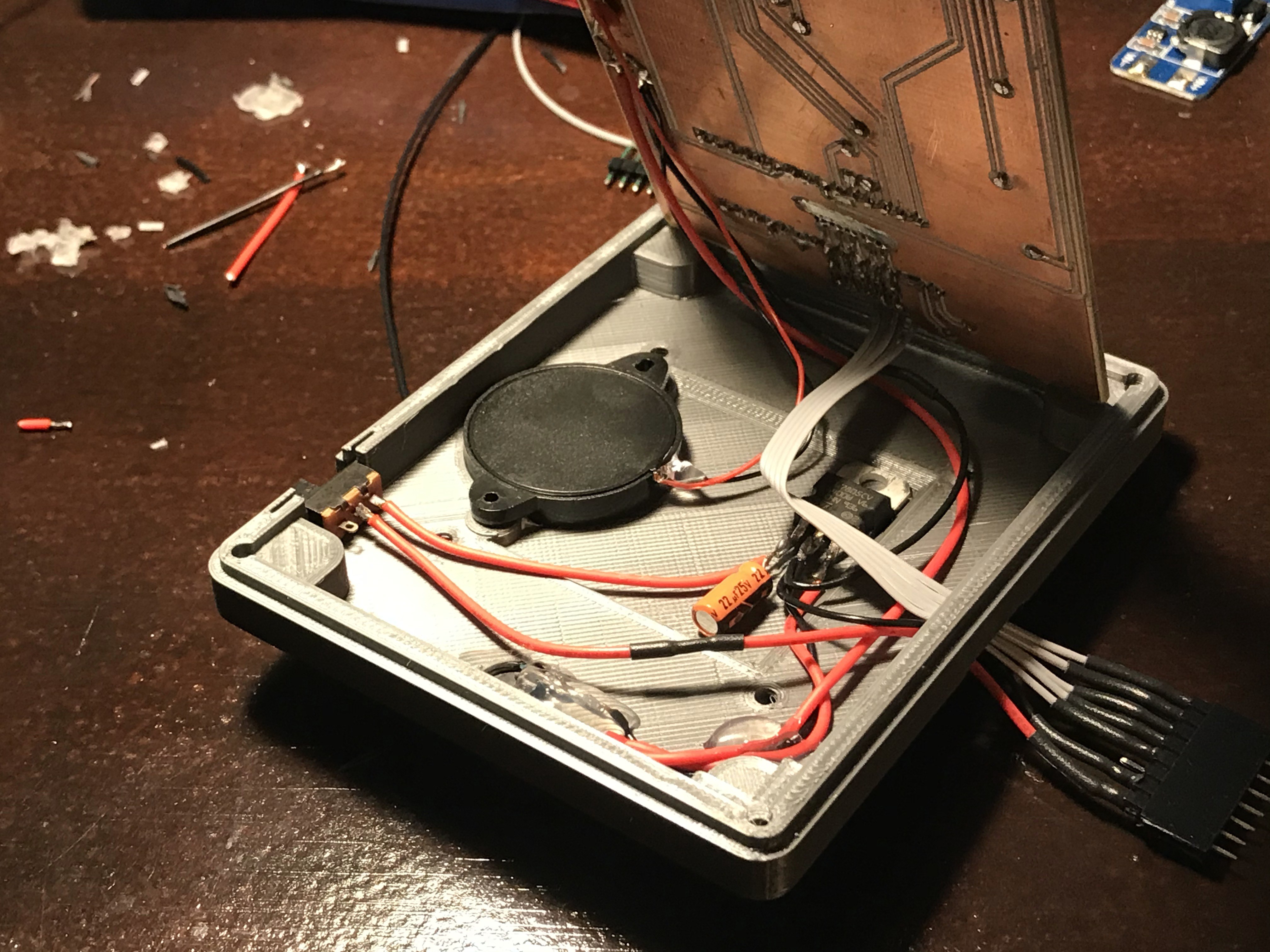
In order to make them more robust, I use my trusty hot glue to fix wires and pins on place (on cheap pin headers, the actual pins tend to fall out when pulled).
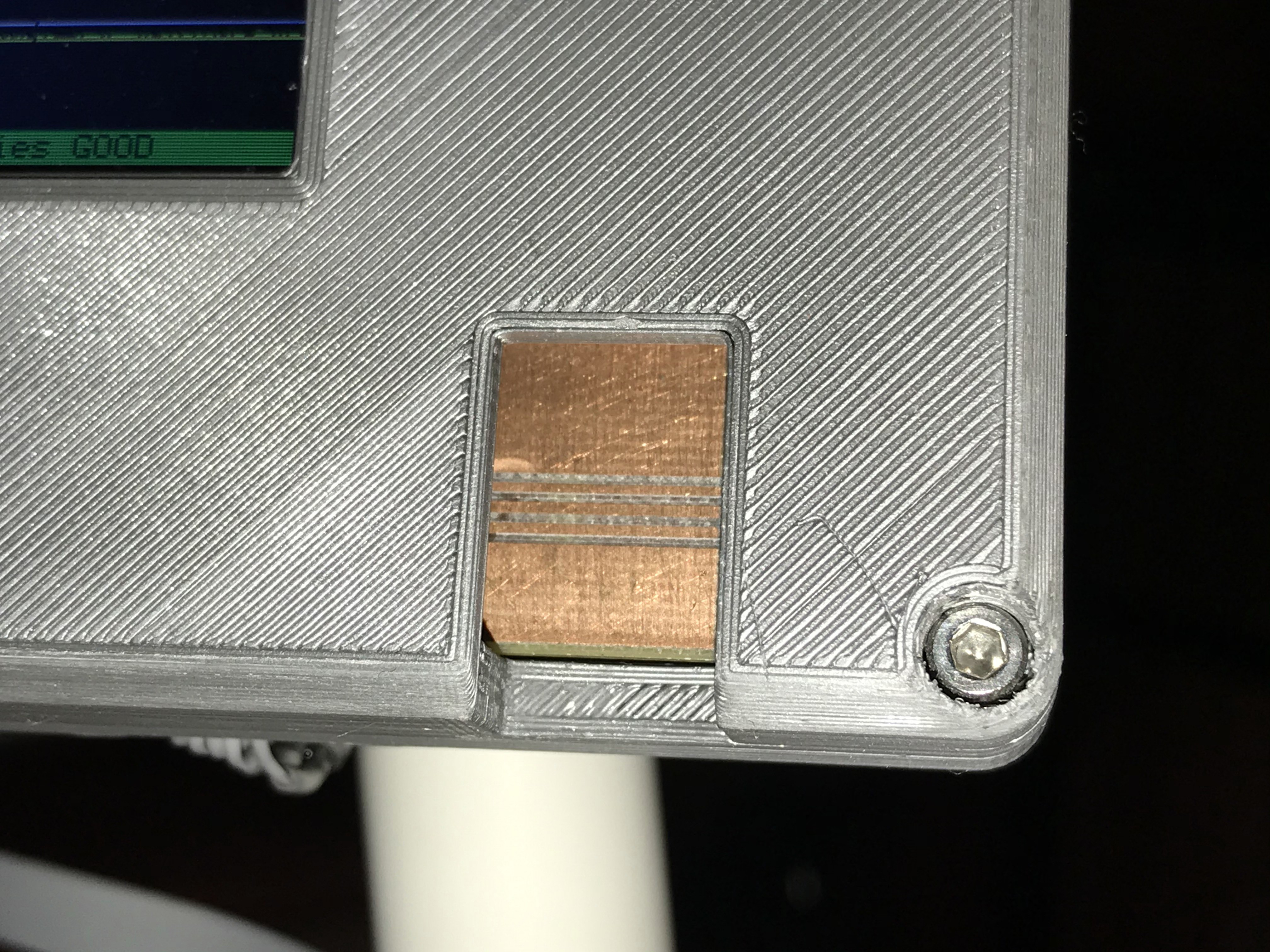
On the front of the module, I designed a cut-out to allow for the Arduino micro USB cable to be connected for programming. Eventually, I'll design a snap on cover for this.
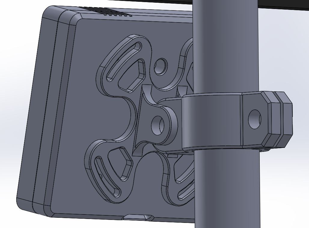
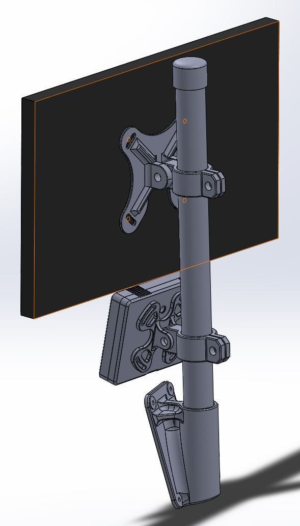
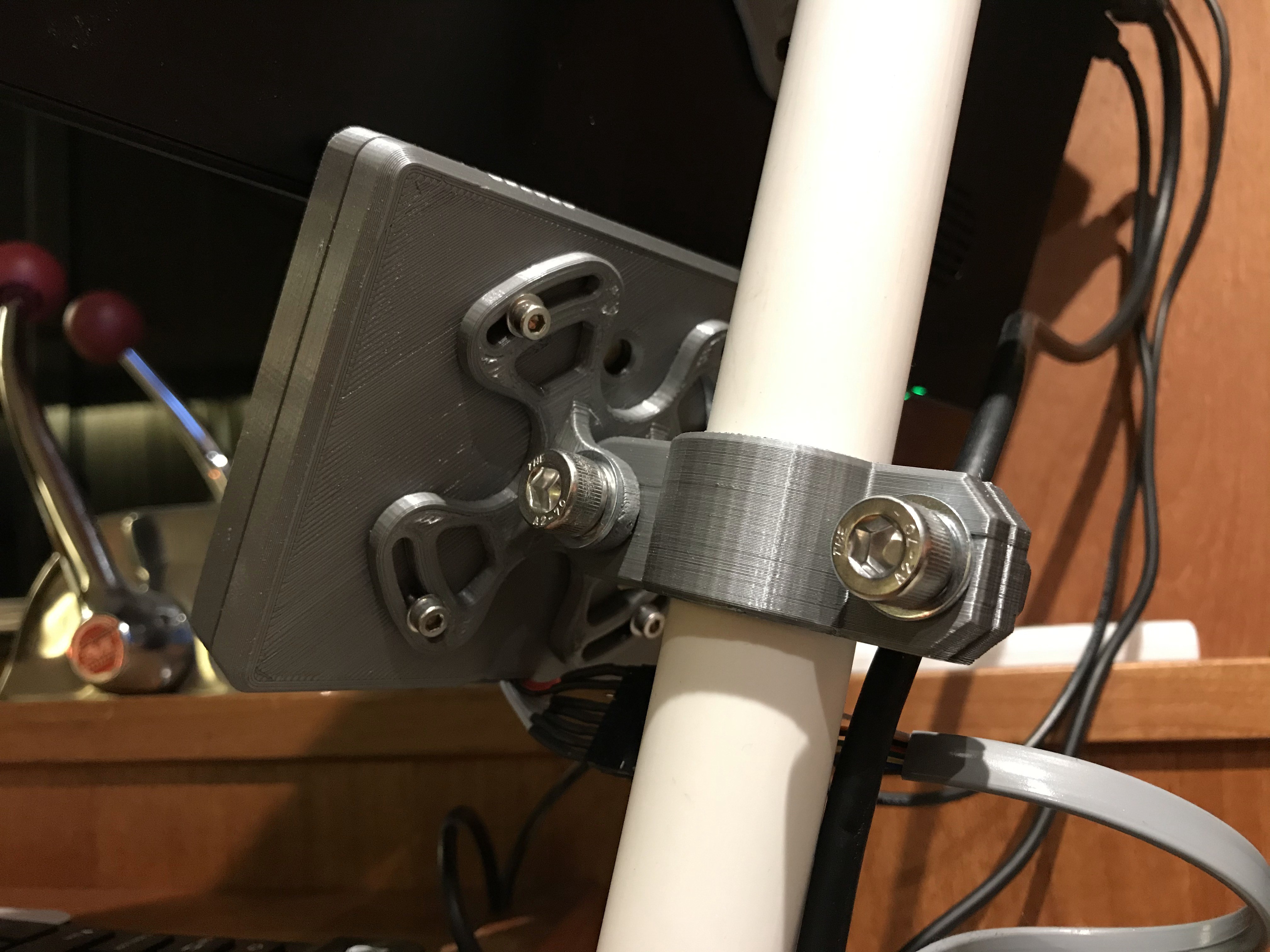
Let's talk about kinematics for a second to explain why I made the module mount rotatable:
When you mount something to a tilted pole and then swing that something around to change the viewing angle, your module will be tilted. That doesn't look good at all. To avoid this, I designed a 15 degree rotation into the rear mounting structure. This allows me to keep the module horizontal despite it's rotation around two axis!
Let's talk software:
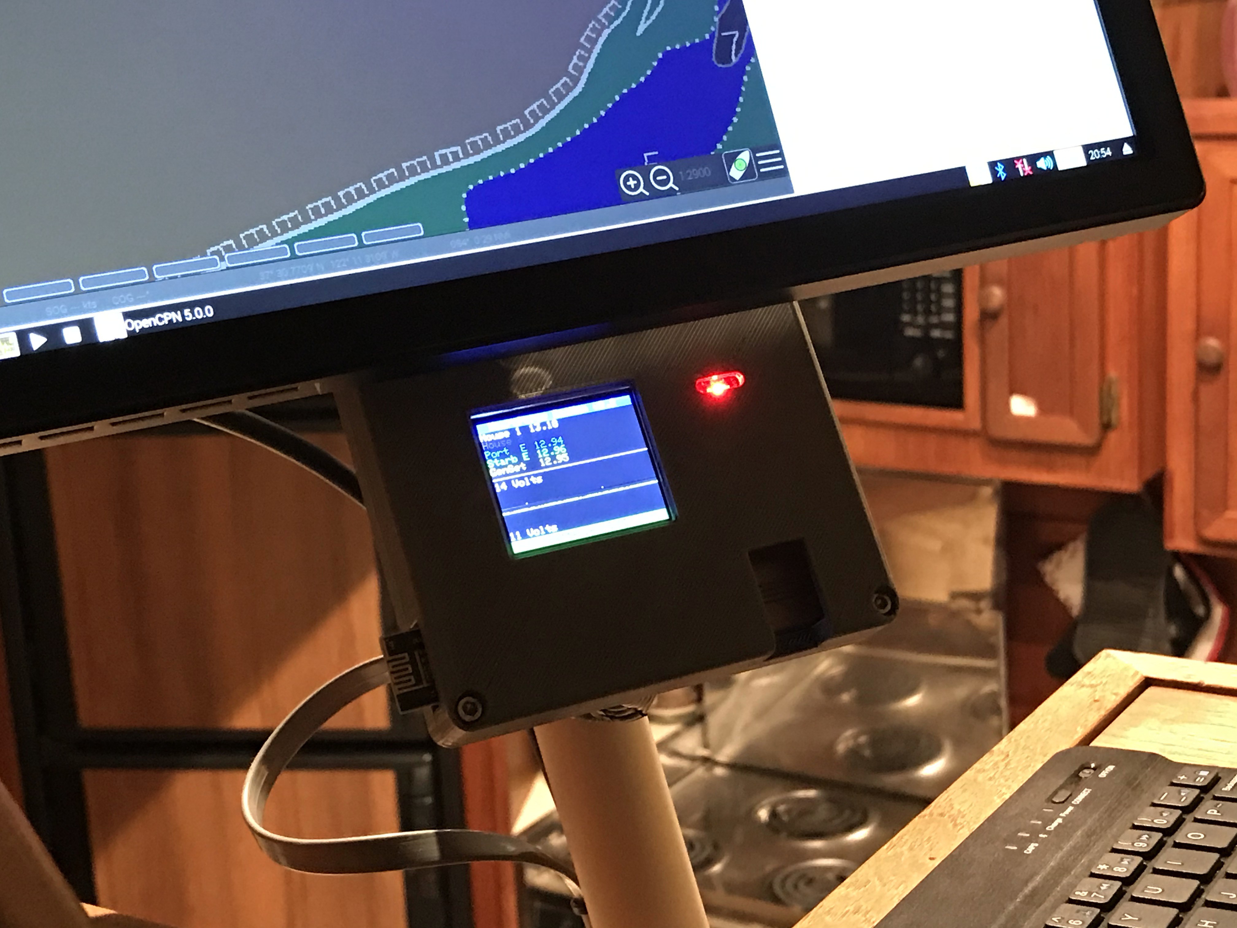
To me, the initial version of this battery monitor looked pretty awful. The Adafruit pixel font didn't look like a product of 2020. I mean. Granted. The tiny screen doesn't permit a modern look but at least I can try to get the best possible results.
During one of my favorite projects I discovered this super high performance TFT Display Library that really works well on my other projects. This library is easily 10x faster than the Adafruit lib and allows some decent graph drawing.
Unfortunately, the Arduino Nano with its 328p has only a 2kb ram and can't handle graph buffers for five batteries. Fortunately, the display is essentially its own buffer since one can just write pixels to it and it will display them no matter what the Arduino does next. So a rolling graph is no problem and very easy to implement!
This one is not very graphical but what happens is the graph constantly rolls from left to right with fresh samples from five batteries at the same time and rolls over on the right edge of the display to start again from the left. To clear the screen, I draw one black 60 pixel vertical line across the graph area to clear whatever the voltage was on any of the batteries on the last round across the screen. The graph progresses at 10 hz and needs about 16 seconds to refresh the screen.
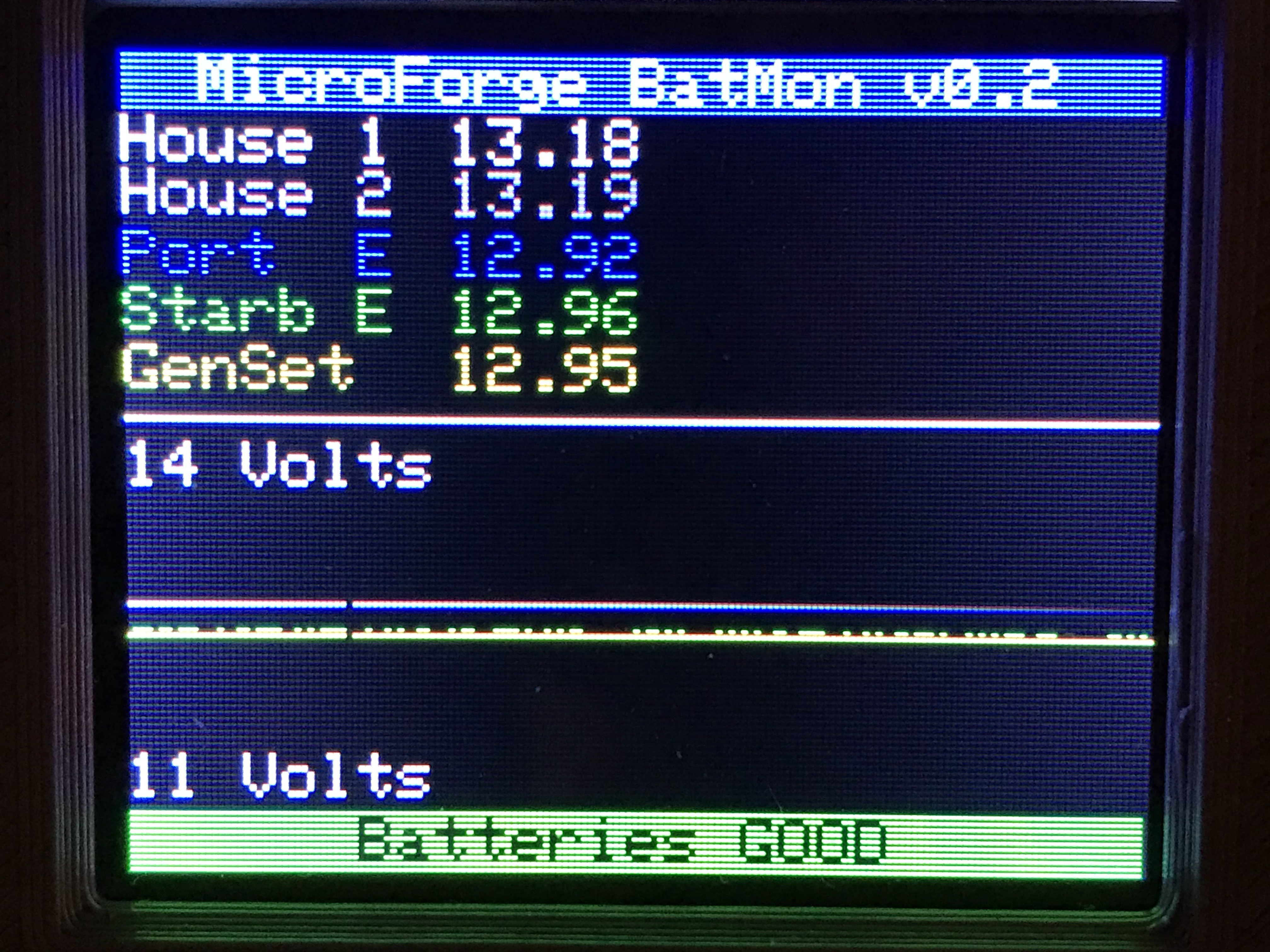
This is great to see charge states and starter phases.
It's not great to see the lifetime of the battery and how it deteriorates. However, that's where the wireless data monitoring using my board computer Raspberry Pi comes in at some point.
Next steps:
I'm thinking about analyzing each battery's state: Charing, discharging, idle, damaged. This would add a lot of value to this project but would also require a lot of research to get right. The top right corner of the screen is reserved for that.
Discussions
Become a Hackaday.io Member
Create an account to leave a comment. Already have an account? Log In.