 Ken Yap
A DTL binary clock
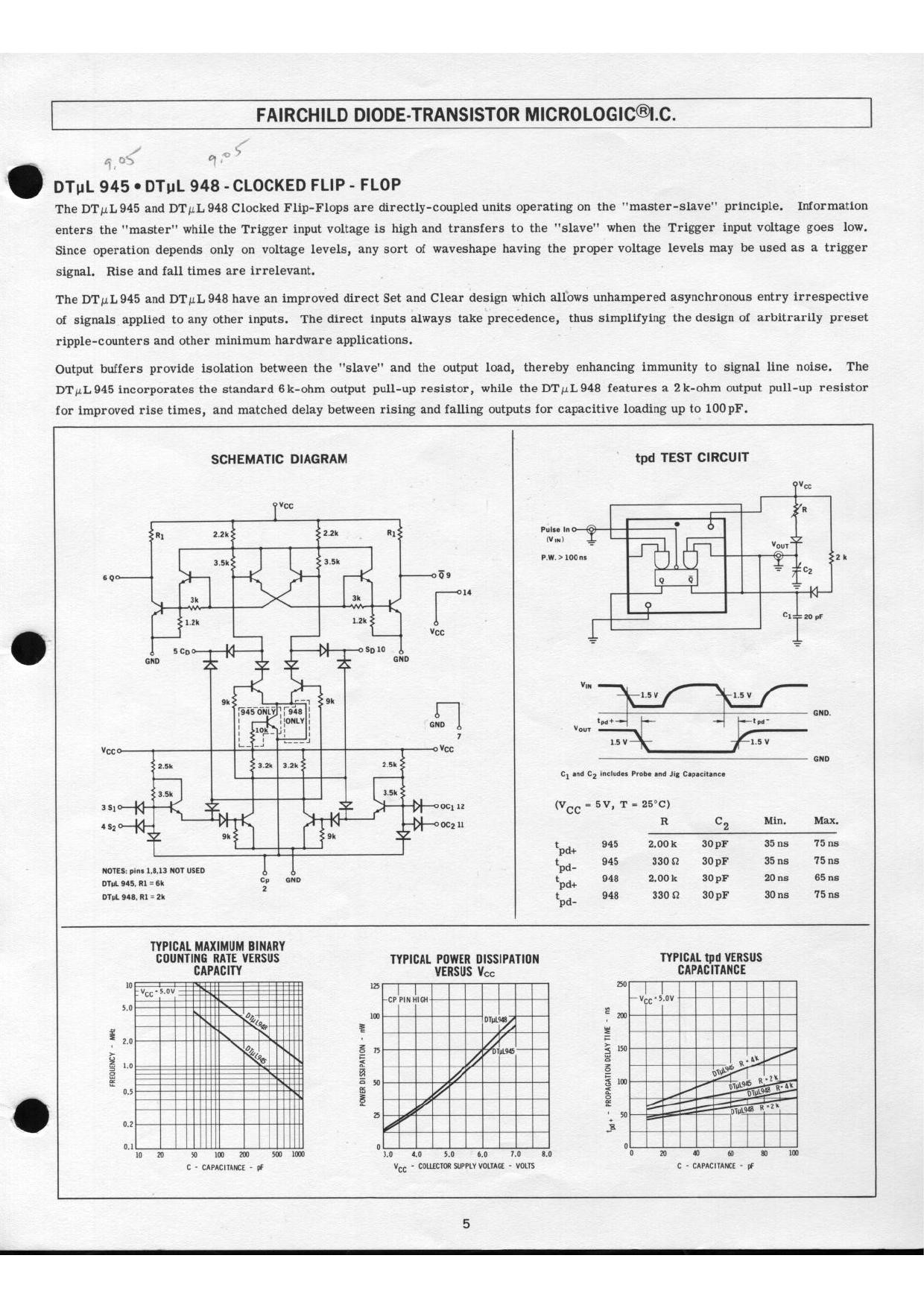
I found that I have a dozen DTµL945 master-slave flip-flops from about 50 years ago in my retro collection. These Diode Transistor Logic (DTL) chips are truly small scale integration. Even TTL packed 4 or 8 flip-flops to a package. What to do with them? Here is the data sheet for it.
Overview
The only viable project I could think of was a binary clock. I can't even do BCD hours and minutes, that requires more chips than I have. I can only do sexagesimal hours and minutes. 0-23 requires 5 bits, and 0-59 requires 6 bits. I also need a 2-input NAND gate to reset the hours at 24 and a 4-input NAND gate to reset the minutes at 60. I have the DTµL830 which has dual 4 input NAND gates. This has the same pinout as the TTL 7420, and in fact I used the library symbol for that. The LEDs are driven directly from the flip-flops.
Designing with DTL is very similar to designing with classic TTL, after all TTL was a development from DTL. The main difference is that there is no active pull up on DTL outputs so rising edges are not as sharp, limiting the speed. For this clock the highest frequency in the circuit is 50 Hz so this is of no consequence.
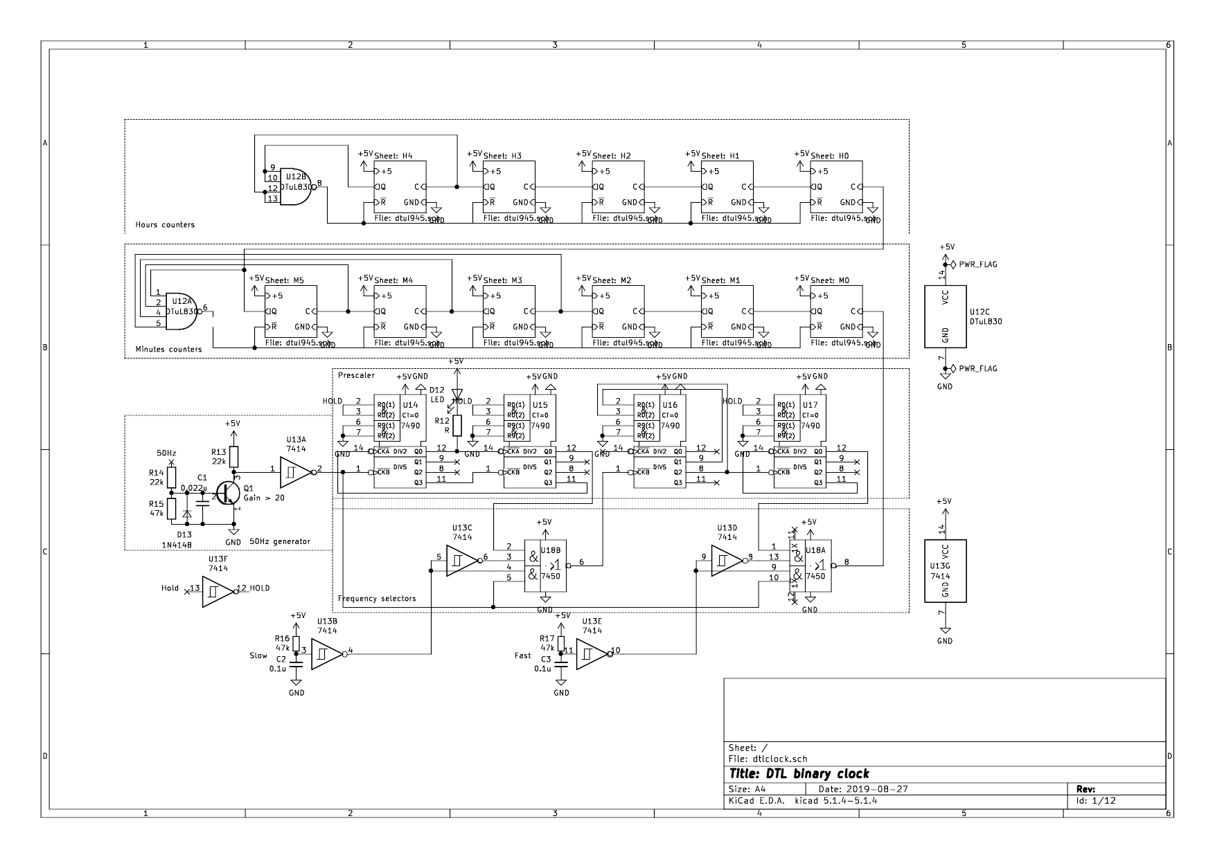
Now the components of the design, starting from the frequency input. Here is the circuit I designed in the first round of this project with blocks indicated. See below for the newer version.
Time reference
I decided on 50 Hz mains so I have to prescale the input by 3000. I can do this with 4 TTL 7490 counters of which I have a lot. This means the design is not pure DTL but still retro. By adding a TTL 7450 dual AND-OR-INVERT gates as two-input selectors I can bypass part of the chain so that the hours and minutes can be set quickly. A TTL 7414 hex schmitt trigger for debouncing the switches and providing the inversion for the 7450 gates completes the line-up. One discrete transistor squares the sine wave from the transformer. For power I have to use an old-school step-down transformer, rectifier, and a 7805 voltage regulator chain, as a SMPS won't provide the 50 Hz reference. These power wall warts are getting rare. If I'll be making more mains frequency driven clocks I may have to put out a call to a local recycling group to snarf all the old power transformers left. 😀
Prescaler
The 7490 has separate divide by 5 and divide by 2 sections, so they can be used in two configurations. The first two 7490s divide by 5 twice then divide by 2 twice. This gets us a square wave rather than a 20% duty cycle wave. This is useful so that the pilot LED has a symmetric blink. If a calmer blink of 0.5 Hz instead of 1 Hz is desired, the LED can be driven from the divide by 2 output of U15 instead of U14. The penultimate 7490, U16, divides by 3, with outputs for 2^1 and 2^0 ANDed to reset to 0 after 2. The last stage U17 divides by 10 (5*2) and the output is a 1/60 Hz square wave, i.e. period of one minute.
Binary ripple counters
The master-slave DTµL flip flops feed the Q and Q' outputs back to the inputs crossed so that each clock pulse will invert the state, thus dividing by 2. The wiring looks hairy but each stage is wired identically. For the minutes the 32, 16, 8 and 4 flip flops go to a NAND gate to reset at 60. For the hours, the 16 and 8 flip flops go to a NAND gate to reset at 24.
I used sockets for the DTL chips in case I need to replace counters or gates. Or rather one counter I have only one spare. 😀
LEDs
The Q' outputs of the binary counters sink current so when Q' is 0 the LED lights up, i.e. when Q is 1. TTL/DTL outputs can sink much more current than they can source. One unit load is 1.6 mA. Most gates drive 10 ULs so up to 16 mA can be sunk.
I used greenred LEDs for the hours and redyellow LEDs for the minutes to make it easier to read. I also used rectangularsmaller LEDs for the high nybble. The pilot 1 Hz LED at the bottom uses an ambera blue LED. It also helps to orient the viewer when many LEDs are off.
Board
Not only did I design the circuit in Kicad/eeschema but I also did the layout in Kicad/pcbnew, even though I won't be ordering an etched PCB but assembling on a perfboard with point to point wiring because this is a one-off as I have chips for only one board. I will be writing more on this, but in short, laying out the board in pcbnew helps with component placement and routing to reduce the amount of wiring. I discovered that I could fit the design on a 120mm x 75mm board with no room to spare. If I had just plunged ahead with putting the chips on the board I would have had to backtrack a lot, whereas adjusting the layout in pcbnew is just desktop work. Good practice for pcbnew too. Exhibit 3 is the board with tracks, exhibit 4 is the 3D depiction of the board.
After I assembled the board in the first round of this project, I discovered that it was intermittent. This should have been no surprise as there is a heap of point to point connections and perfboard makes it hard to get reliable solder joints.
I really like this design as mains frequency is the timing reference. I was hoping to display it along with my plasma clock as ancient IC technology that still works and can outlive me. In my experience there are only several timing sources that do not require periodic correction: mains, Internet, GPS, and an accurate TCXO like the DS3231. I'm of course excluding exotic sources like rubidium oscillators. Run of the mill crystals drift enough to require correction every so often. A throwback to the days of adjusting wrist watches, come to think of it.
It would be easy to convert the schematic, already drawn in eeschema, to a PCB layout, but the area required exceeds the cheap 100x100 mm limit. A one off order might be acceptable, but then I would have to order a minimum of 5. As I have only one set of DTL chips, 4 boards would be wasted. This irked me.
I mulled ideas to reduce the waste, including mounting the DTL flip-flops on daughterboard modules vertically, and so forth. Then I hit upon the idea of partitioning the circuit across two boards < 100x100 mm. Not just any kind of partitioning but one where both halves are nearly identical, otherwise I would have to get 2 designs made, wasting 8 boards. If I could spread the circuit across two identical boards, but populated and jumpered differently, then I would only waste 3 boards out of 5.
I took on the design challenge with relish. The flip-flops and counters are obvious candidates for spreading across two boards. The rest of the circuit could stay on one board. This meant a 3-3 partition for the minutes flip-flops, and a 2-3 partition for the hours flip-flops. Fortunately the overflow detection uses only the top 4 bits for minutes (2^5 to 2^2) and the top 2 bits (2^4 and 2^3) for the hours, so the inputs to the NAND gates don't have to cross the board boundary. (The 2^2 output is available at the input of the 2^3 flip-flop in case you are wondering.)
There are 4 7490s. The first two divide by 100, with a seconds LED driven at 1 Hz. The last two divide by 30. So it was a matter of some jumpers around one 7490 to select divide by 10 or divide by 3.
These connections need to be provided on each board:
- Power, +5V and GND
- The carry between 2^3 and 2^4 for the minutes and hours chains
- The carry from minutes to hours
- The minutes input taken from the prescaler output
- The minutes and hours overflow reset lines
- Count hold
- The inputs and outputs of the slow and fast slew frequency selectors
Here is the schematic for each board that I ended up with.
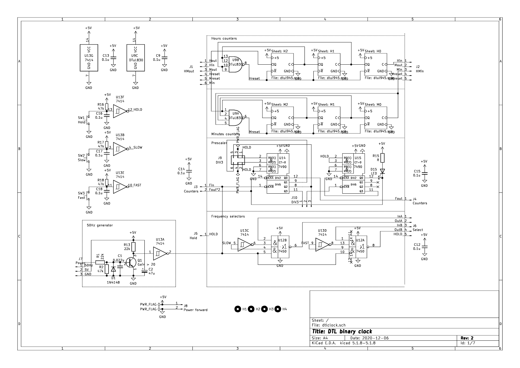
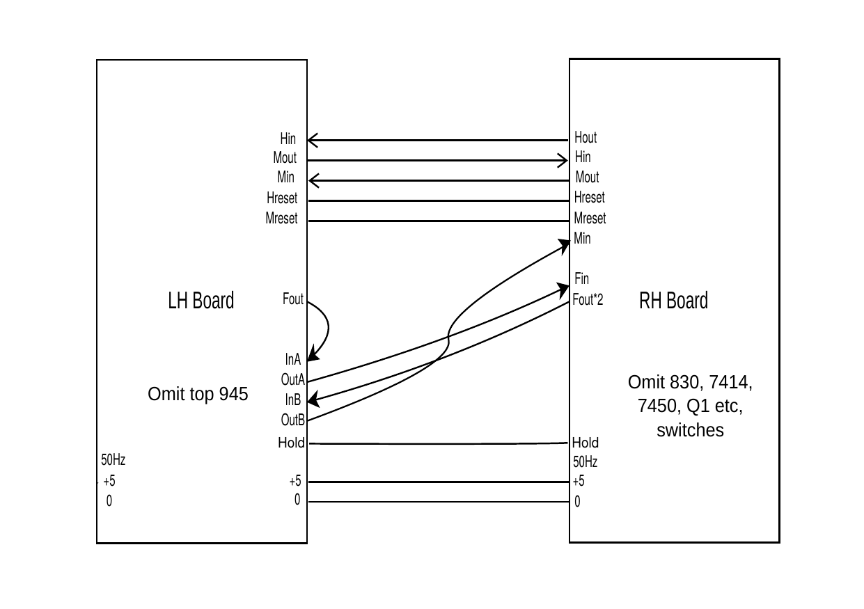
Connections may be intra or inter board. In the end the design had about a dozen wire connections, and 3 onboard double pole jumpers. I drew an interboard connection diagram which helped me spot some errors. Some connection points are duplicated at both the left and right edges of the board to reduce wire length.
Here is the inter-board connection diagram:
I had to resort to a couple of tricks, such as mounting the current limiting resistor for the LEDs on the bottom of the board under the LEDs, to fit in the space.
I looked over the schematic and checked the nets in pcbnew many times over several days. It really does your head in to have to think in terms of left and right boards. I corrected several mistakes due to the partitioning. If those had not been fixed, I would have had to rework by cutting traces and adding adhoc connections.
Despite the thorough checking I felt a bit of trepidation when uploading the Gerber files. It will take a few weeks to find out if I have missed anything. I could find out sooner if I had been willing to pay courier charges but I'm cheap. I picked Ocean Smile, a PCB fab that I have given my custom to before. I chose them because the charge for 5 boards + shipping was the lowest, just under $10. This board is not critical with respect to PCB features, as it's all 0.1 inch pitch THT.
In preparation for assembly of the new boards, I retested the DTL flip-flops, the TTL 7450 and 7490s using custom Arduino sketches, found in the files section. Writing such sketches is a good way to confirm that one has understood the behaviour of the chip, and of course that the chip is good. The DTL 830 and TTL 7414 were tested using my TL866 (E)EPROM programmer which can test a selection of logic chips.
Coda
Exhibit 5 is a photo of the assembled board. Notice the rounded corners of some IC packages; you don't see that these days. I have to say though that the experience of point to point wiring has made me so over this tedious method of circuit assembly. Part of the problem is that the board is so dense. For perfboard you need more space. But I had only enough chips for one specimen and the board was over 100x100 mm so I didn't want to spend a lot of money on a proper PCB. In future I will breadboard the hell out of a design before sending off for fabrication. Also make designs as firmware configurable as possible and arrange to build at least 5. My friends will gain. 😀
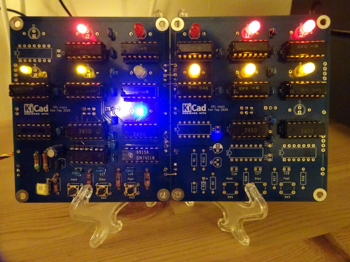
The boards duly arrrived about 4 weeks after ordering, quite fast considering the end of year shopping rush affecting transport, and were assembled. Despite my misgivings, the partition scheme worked well, you can see the wire stitching and that the left hand board holds the unduplicated logic. I like the blue soldermask and I'll consider this colour when there is no premium. Here you see the board on a acrylic easel. Interesting how red LEDs often don't come out right in digital photos.
There's quite a good chance, barring an apocalypse, that the DTL chips can continue to work for another 50 years, longer than I will. 😀