 Ken Yap
In the DTL binary clock I run the 50 Hz mains frequency through a squarer consisting of a transistor and a schmitt inverter. Here is the circuit:
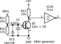
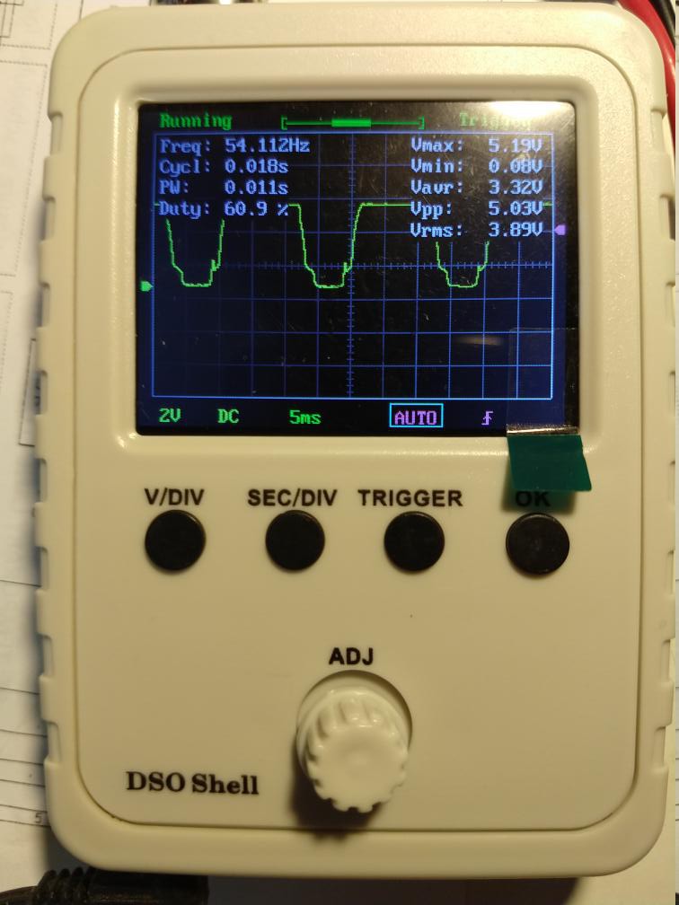
There is a diode to limit the negative excursion of the base voltage. The first version worked fine. A second version using another set of components (the first set was set aside as working components for building a board) worked unreliably. I put a DSO on the collector of the transistor and saw this strange waveform.
Finally it occurred to me to take the transistor off the breadboard and test it. It was then I realised my mistake. I had reached out and taken a transistor from the PNP bottle rather than the NPN bottle. But how did it even partly work?
One of the questions a beginner encounters is if a NPN or PNP transistor has two junctions of the same type, how is the emitter different from the collector? Could we swap them around? Well, the difference lies in the doping of the emitter and collector, as this posting explains. And of course the B-E junction is forward biased and the B-C junction reverse biased in normal operation. So if we swap them around we would get a rather poor transistor with very low gain.
Redrawing the circuit shows that I was running the PNP transistor in a emitter follower configuration. So what I took to be the collector was really was the emitter and its voltage was tracking the base voltage, so followed the input waveform.
Putting in a NPN transistor made the circuit work as designed.
Discussions
Become a Hackaday.io Member
Create an account to leave a comment. Already have an account? Log In.