 Ced
CedAfter watching many Youtube videos on Breadboard TTL computers, I noticed that there is often a misundestanding regarding the type of Register TTL chips available and what are their best use cases.
The most common is the 74HCT173. This one brings everything you need from a register IC:
- 4 bit register
- Common clock signal (rising edge)
- Input enable signal (/E1 and /E2)
- Output enable signal (/OE, /OE2)
- 3 state output
- Asynchronous master reset
The only drawbacks are that this IC is only 4 bits and the pinout is really weird.
However, in many breadboards computer, designers use the 74HCT273 without really understanding the differences. The 273 has the following features:
- 8 bit register
- Common clock signal (rising edge)
- Asynchronous master reset
This IC has no Input Enable signal and no Output enable signal. What it means is that at EACH clock signal, the input is latched and that the output is always on. In other words : The output mimics the exact value of the input as it was on the previous rising edge of the clock.
No big deal regarding the output as we can use a 74HCT245 to buffer the bus.
The issue is with the input. Do we want to latch the input value at each rising edge of the clock ? Most of the time NO ! We want an input enable signal. Some would say, it's easy: just use an AND gate between the clock and the input enable and it will work. This is not true and should not be done. Here's why:
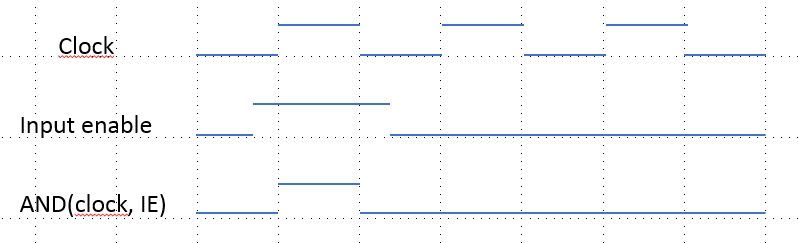
Example 1, the Input Enable is activated a bit before the clock rises. This is basically what we would expect. The input Enable signal activates the clock, the register latches the value on the bus at the time of the rising edge. The AND between the clock and the Input Signal looks like the clock when activated:
Example 2, the Input Enable signal is not really aligned with the clock, it misses the first rising edge and stays on for the second (note that the duration of the Input Enable is the same as above):
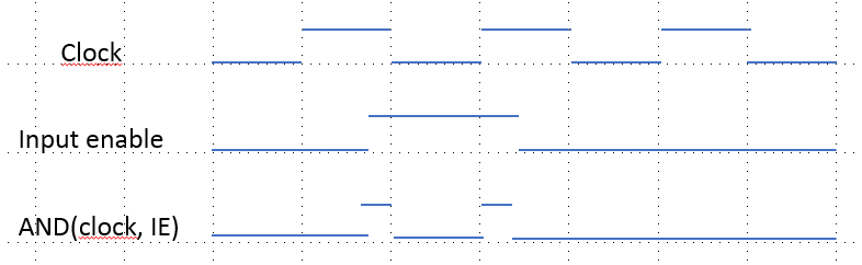
In that situation, the AND signal provides 2 rising edges. Therefore the register will latch (if fast enough) the information twice at points in time that are not expected. it will miss the first rising edge of the clock, latch on the rising edge of the Input Enable signal (unexpected) and then latch again on the second clock rising edge.
It is not recommended to apply gates on the clock signal to enable/disable clocks for the microinstructions. The 74HCT273 is not recommended in our use cases.
However, there is a nice IC that matches better the needs for typical registers: the 74HCT377. It provides the following features:
- 8 bit register
- Common clock signal (rising edge)
- Input Enable signal (/CLKEN)
It still lacks some nice features of the 173 (master reset, output enable) but it is quite convenient to get 8 bits with Input Enable.
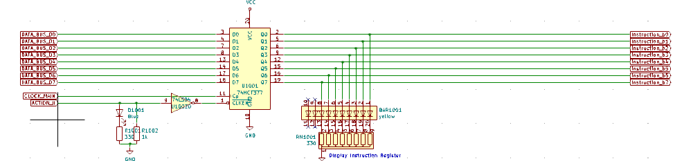
Here is a good example of the usage of the 377 for our Instruction Register (it doesn't need to be cleared and the output is always on):
Discussions
Become a Hackaday.io Member
Create an account to leave a comment. Already have an account? Log In.