 Ced
CedNow that that first version of my CPU is running, it is time to fix some issues. One of them is manual switches and debouncing.
I will not write one more article about debouncing as all this is very well detailed in the great article by Elliot Williams Debounce your noisy buttons.
In this first version of my CPU I ended up with the following switches
- Bus Publish : This pushbutton published the value of a dip switch to the bus
- Master Reset : This pushbuttons resets the computer
- Memory manual Write : This pushbutton writes the data set on the data dip switch at the memory address set on the address dip switch [PRO mode only]
- PROG/BUS selector : this is a two way selector used to program the memory (PROG mode) or to use the memory through the regular bus and Memory Address Register (BUS mode)
- MANUAL / AUTO clock selector : this is a two way selector used to select between the automatic clock (slow or fast) or the manual pulse pushbutton
- SLOW / FAST clock selector : this is a two way selector to swicth between the 555 base slow clock (between 0,5Hz and 300 Hz) and the fast cristal oscillator based clock (1 Mhz) [valid for Auto clock mode only]
- MANUAL / AUTO uCode selector : this is a two way selector disabling the microcode decoder in order to use manual action signals (debugging purposes only)
3 are pushbuttons and 4 are two way selectors (slide buttons).
In is articule, Elliot explains how to debounce using an RC (Resistor/Capacitor) circuit and a schmitt trigger inverter. The inverter can be found in the 74HCT14 IC.
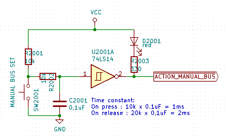
Here is an example of a complete debouncer. Note that the signal is inverted : when pressing the button, the signal ACTION_MANUAL_BUS goes low.
Here a short description of how it works :
When the switch is open, the capacitor is loaded through the 10k + 10k resistors and reaches VCC. The output signal is then 0V (inverted input)
When the swicth is pressed, the capacitor is unloaded through the 10k resistor, it will therefore take 1 ms to reach 1/3 VCC and trigger the change of state of the inverter
When the switch is released, the capacitor is loaded again, it will reach 2/3 VCC in 2ms and trigger the change of state of the inverter.
For the slide swicthes (type is break before make), we need to prevent any oscilation between the two states and prevent an unknown state. The best solution here is a simple SR latch.
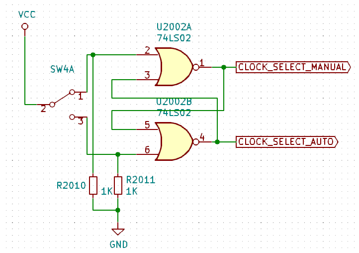
An SR latch (in this cas an SR NOT latch as it is built using 2 NOR gates) can only be in 1 of 2 states.
When moving the switch from on position to the other, what may happen is the following:
- bounce off the first state
- stay undefined (in between the two states)
- bounce on the second state
In such a situation, the SR latch will prevent any oscillation following the reasoning:
- When the switch bounces off, the latch will stay in the same status (set or reset)
- when the swicth is undefined, the latch will stay at the same status
- the first time the witch touches the other positon the latch will toggle but even if the switch bounces it will stay in that second position.
So in the end, I have built a dedicated breadboard with all the swicthes, RC circuits and IC to debounce all and have perfectly clean manual signals.
Discussions
Become a Hackaday.io Member
Create an account to leave a comment. Already have an account? Log In.