Close
0%
0%

Universal IPS Display Breakout Board

ST7789 and ST7735 Breakout Board

Similar projects worth following
Breakout Pins

Most of these displays have the same pins.

My next revision will have the 8-bit pins broken out

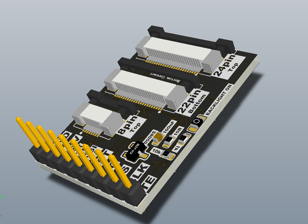
0.96"     ST7735       80x160      8Pin

                            Purchase Link

Pinout

       CAD Models

0.96"    ST7735       80x160     13Pin

                            Purchase Link

     CAD Models

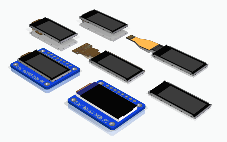
1.14"  ST7789V       135x240     13Pin

                             Purchase Link

      CAD Models

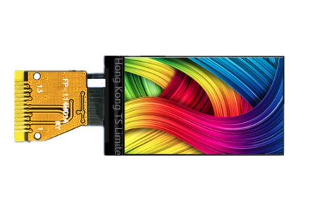
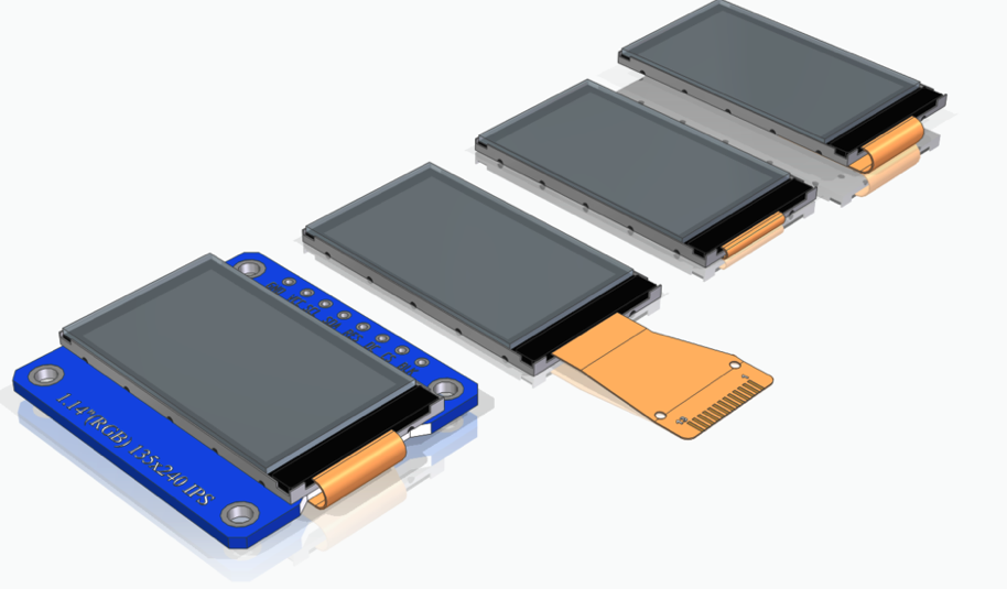
1.3"    ST7789      240x240        12Pin

                   Purchase Link

     CAD Models

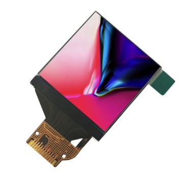
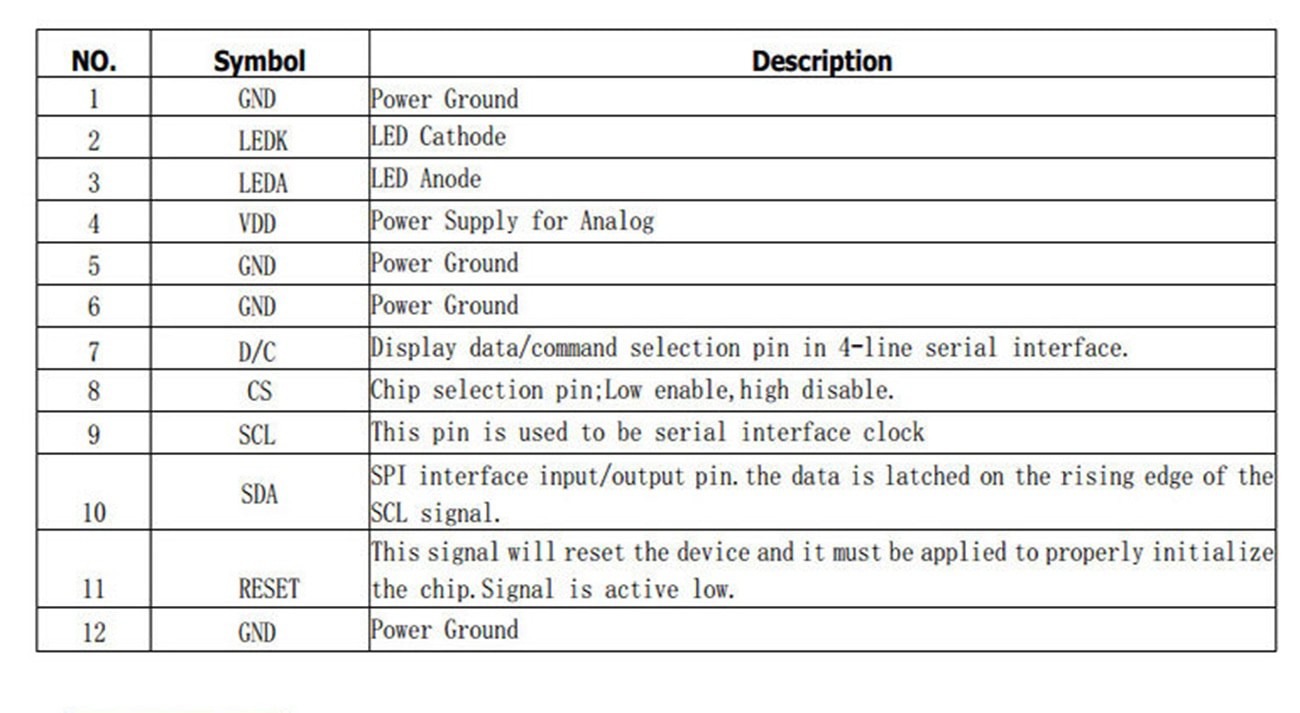
1.3"    ST7789    240x240      24Pin

                            Purchase Link

     CAD Models

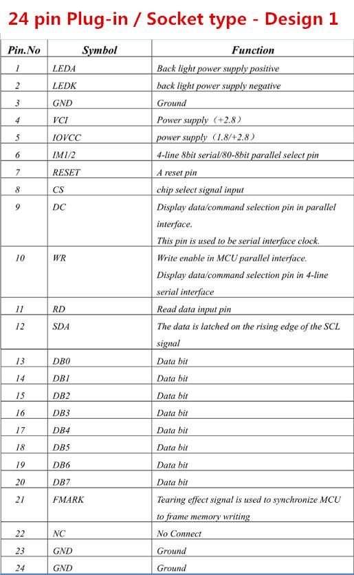
1.54"   ST7789     240x240    12Pin

                    Purchase Link

     CAD Models

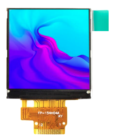
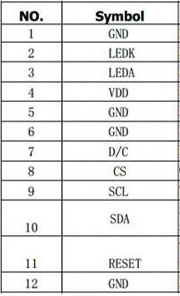
1.54"   ST7789    240x240    22Pin
                    Purchase Link

     CAD Models

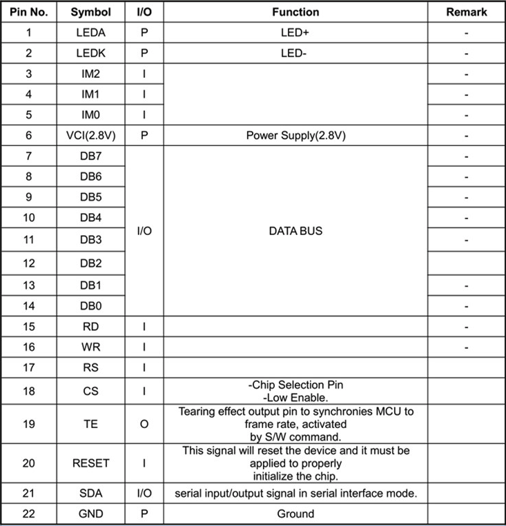
2.0"    ST7789     240x320    12Pin

                     Purchase Link

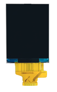
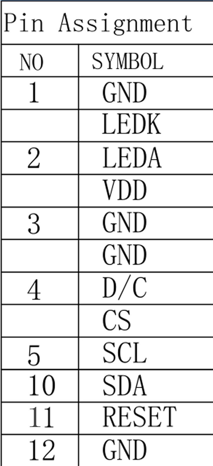
2.0"     ST7789    240x320    22Pin

                        Purchase Link

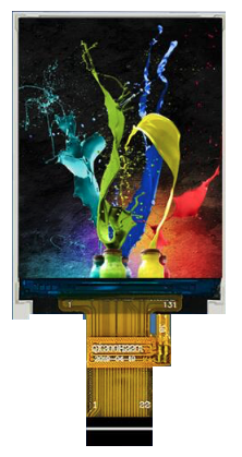
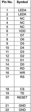
2.4"    ST7789   240x320    24Pin
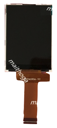
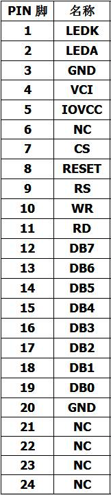
                           Purchase Link

LCD IPS - Breakot Board - Rev1.zip

Gerber files - Oshpark

Zip Archive - 112.79 kB - 11/11/2019 at 18:28

Download

  • 1 × 1k 0603 Resistor 0603
  • 1 × 10k 0603 Resistor 0603
  • 1 × 10R 0603 Resistor 0603
  • 1 × 0ohm 0805 Jumper Resisto 0805
  • 1 × S8050 Discrete Semiconductors / Transistors, MOSFETs, FETs, IGBTs

View all 10 components

View project log

Enjoy this project?

Share

Discussions

Stephen Walsh wrote 11/10/2019 at 06:22 point

Interesting project and timely for me doing something similar. In my case I'm trying to hedge my  bets (and avoid researching the multitude of displays available). Seeing what you have come up with has been helpful so thank you for sharing. When I'm confident with the pin outs I get to I'll share those as well.

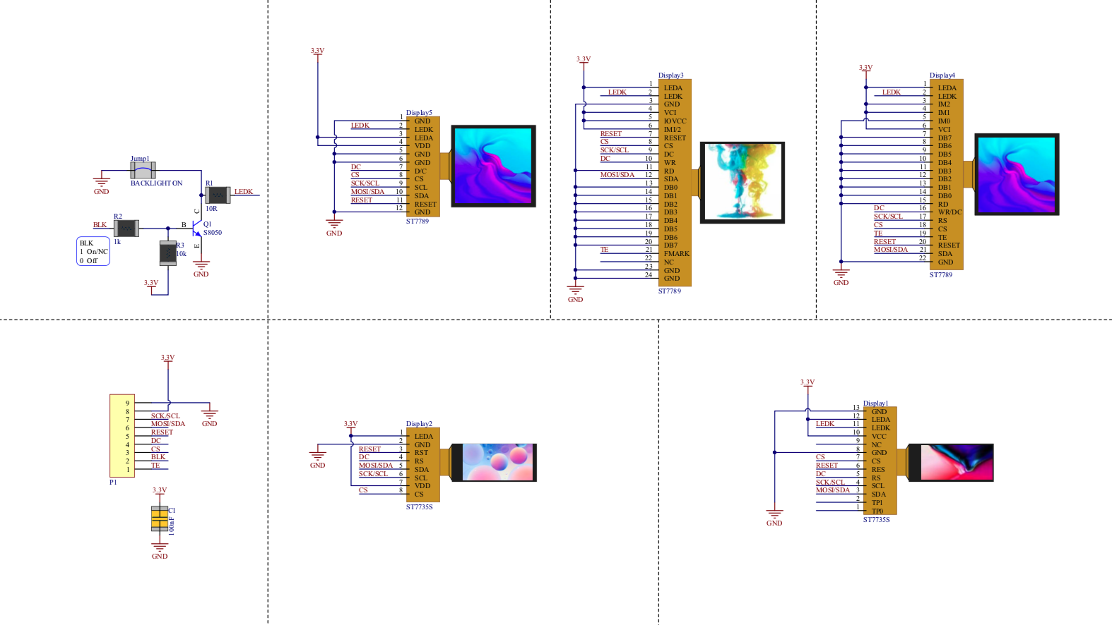
One observation for display 3, and this may or may not be an issue but having seen it I'd be rude not saying something: the DC pin and signal don't match up and the CLK is on the DC pin. This is probably perfectly correct and just an artifact of the mux'ing on the pins but I mention it just in case.

Thanks again.

  Are you sure? yes | no

John Loeffler wrote 11/10/2019 at 14:15 point

I agree, That is the one I tested in the video and it works.  The schematic model is what I got from the Aliexpress Supplier which is probably not correct.  The symbol may not be correct but the schematic works.  I used the schematic from Adafruit to verify the pinout 

(https://cdn-learn.adafruit.com/assets/assets/000/079/156/original/adafruit_products_1-3in_IPS_TFT_Sch.png?1565202407)

  Are you sure? yes | no

Similar Projects

Does this project spark your interest?

Become a member to follow this project and never miss any updates