Close
0%
0%

TTL binary clock

A binary clock made from TTL chips from the 70s and 80s

Similar projects worth following
A follow up to my DTL clock, a more practical design I can make for geek gifts

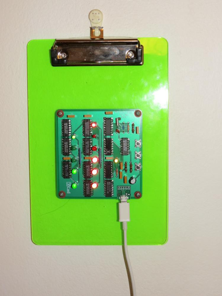
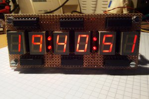
After my DTL binary clock I decided to make a TTL binary clock along the same principles. I have enough old TTL chips to make a few to give to geek friends. I can tell them that this clock can outlast me so it will be a memento. 😀

By using dual D flip-flop 7474 packages I can fit it all on a 100x100 mm board for cheap PCB fabrication.

Old-school transformer wall-warts are in short supply though. I have harvested a lot of 5V phone chargers from the local e-waste bin but these are modern switching mode power supplies. This is good as they are lighter and more efficient but I have to find another timing source.

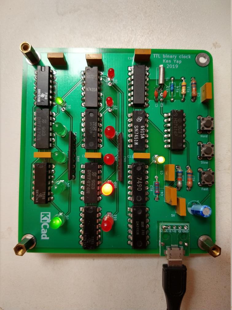
A trawl through my junk box revealed lots of 32768 Hz crystals extracted from PC real time clock circuitry. I found that the CD4060BC oscillator and 14 stage divider is still available cheap. So I have designed a clock generator around this. The final output is 2 Hz, so a 7490 and a 7493 are used to divide by 120 to get a 1 minute period signal. The usual chain of flip flops follows: A 6 stage counter divides by 60 to count minutes, resetting at 60. A 5 stage counter divides by 24 to count hours, resetting at 24.

There were some issues with getting the crystal to oscillate on the breadboard, documented here. It should work on the PCB, where I have ensured the required electrical isolation.

One drawback is that the long term accuracy is not as good as the mains. If we assume a worst case 20 ppm error in the crystal, this means that in a year (about 30 million seconds) it will deviate by up to 600 seconds (10 minutes) from the true time. On the average it should be less, but this means that the clock should be adjusted every month or two.

LEDs are driven directly from the Q' output of the flip flops. Modern LEDs are so efficient that I can run them at about 2-3 mA well within the current sinking capability of TTL logic. I used 1 kΩ resistor networks to save space and reduce soldering.

As with the DTL clock, faster clock frequencies are routed by switches to fast set the hours and minutes.

5V power input is via a micro USB connector, taking advantage of readily available USB A to micro USB cables.

  • Mounted and ready to gift

    Ken Yap12/17/2019 at 08:53 0 comments

    I mounted a couple on A5 plastic clipboards each a couple of dollars from the local office supply store. They have a tab to hang on a wall hook.


    One recipient elected to mount the board on his gift lower down to have space above to clip notes. He joked that he could now write notes like: Fed the cat at 13:27 which is the time shown above in hex.

  • Working correctly now

    Ken Yap11/18/2019 at 10:31 0 comments

    In the last log I complained how the 1 Hz square wave was glitchy and making the clock run fast. I thought about it and realised I had not checked the fan out of the CD4060 2 Hz output feeding the 7450 multiplexer. Turns out that the CD4060 is only rated for a 2 LS gate fan out. Unfortunately the 7450 I used is standard TTL, so effectively 4 LS loads or 1.6 mA. This was causing logic low to be too high and making the gate levels marginal.

    I don't want to rework this board, at least not now, so I added a 4k7 pull down resistor at that gate (pin 1 of the 7450) to assist with logic 0. Now the signal is stable. In the remaining boards I'll be using a 74LS50 which will be fine. I'm running out of old standard TTL chips anyway.

    I would have caught this issue at the breadboarding stage, except that I didn't test the combination of the CMOS output with TTL input due to the issue of the 32.768 kHz crystal not oscillating on a breadboard which I have previously blogged.

    Lessons for me: When mixing logic families, check the logic levels and loading limits, and the breadboard should test as much of the real operating circumstances as possible.

    Declaring this project completed. I may write a page or two when I find a good presentation for making gifts. I'm considering mounting the board in a wooden photo frame that sits on a desktop.

  • Assembled PCBs

    Ken Yap11/14/2019 at 22:20 0 comments

    I got the PCBs a while back from a recent Elecrow offer. I ordered 5 PCBs and was delivered 7. Hope I have enough old TTL chips to populate them all. The power is supplied from a 5V phone charger via this micro USB socket.

    I populated a couple of boards. I soldered LEDs to one and powered it on. The copper pillars are to hold the board a certain distance above the table while I soldered the LEDs in so that they would all be the same height above the board.

    Unfortunately while the counters work correctly, the 1 Hz LED sometimes blinks erratically, with spurious pulses, which cause the counters to speed up. Have to bring out the DSO to see where the extra pulses are coming from.

    I also noted that I have to use a decent micro USB cable, the voltage drop across cheap ones is significant.

    Edit: A few minutes later: Now the clock has settled and the 1 Hz LED is blinking at a steady rate. I hate it when circuits "fix themselves" like that. I'll leave it running to see if the glitch has gone for good. Probably not. 😿

View all 3 project logs

Enjoy this project?

Share

Discussions

Dan Maloney wrote 11/27/2019 at 16:34 point

With all those decoupling caps and resistor networks it has a proper TTL look to it, doesn't it? What kills me is that I threw away probably everything needed to make something like this when I moved three years ago. Chips with date codes from the 1970s - I just pitched them. Shameful...

  Are you sure? yes | no

Similar Projects

Does this project spark your interest?

Become a member to follow this project and never miss any updates