Close
0%
0%

TTL/CMOS Linear LED Clock

A TTL/CMOS based clock that displays the time along a 60 LED bargraph.

Similar projects worth following
A TTL/CMOS based clock that displays the time along a 60 LED bargraph.

I like clocks. I like LEDs. I like mucking around with circuits. I want to make a clock that displays the time along an LED bargraph without using a microcontroller.

Only minutes will be displayed - I can always (usually? maybe I'll find out) tell the time within an hour, so displaying minutes is enough for this clock.

A collection of useful links...

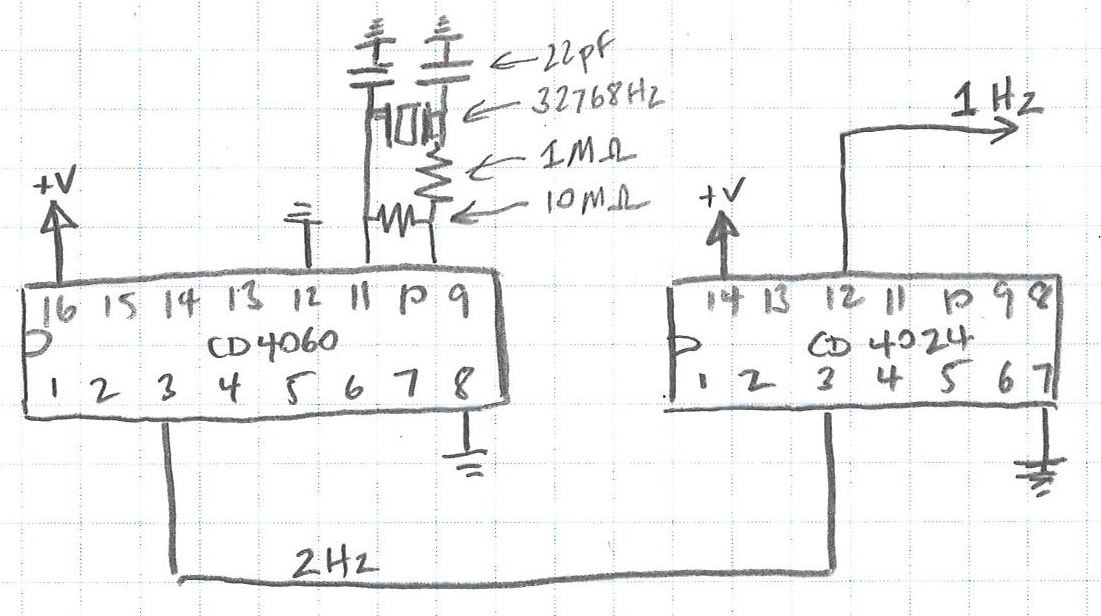
http://mysite.du.edu/~etuttle/electron/elect48.htm - Good description of using CD4060 and CD4024 to divide a 32768Hz crystal to give 1Hz.

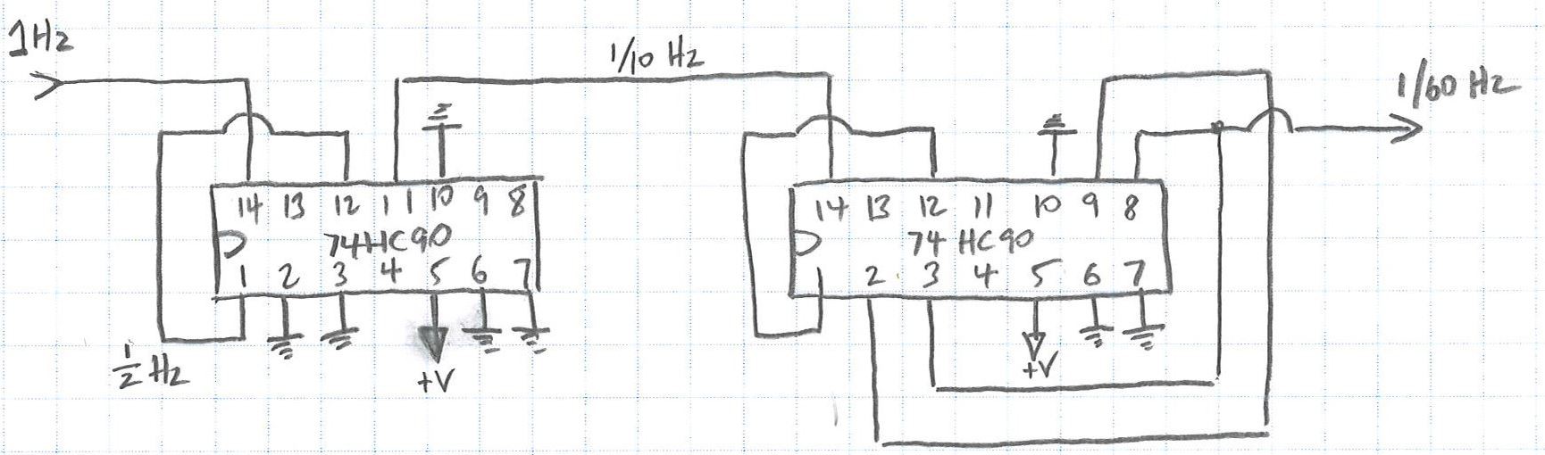
http://users.otenet.gr/~athsam/frequency_divider_with_7490.htm - Awesome page showing how to configure a 74HC90 to divide by any number between 2 and 10.

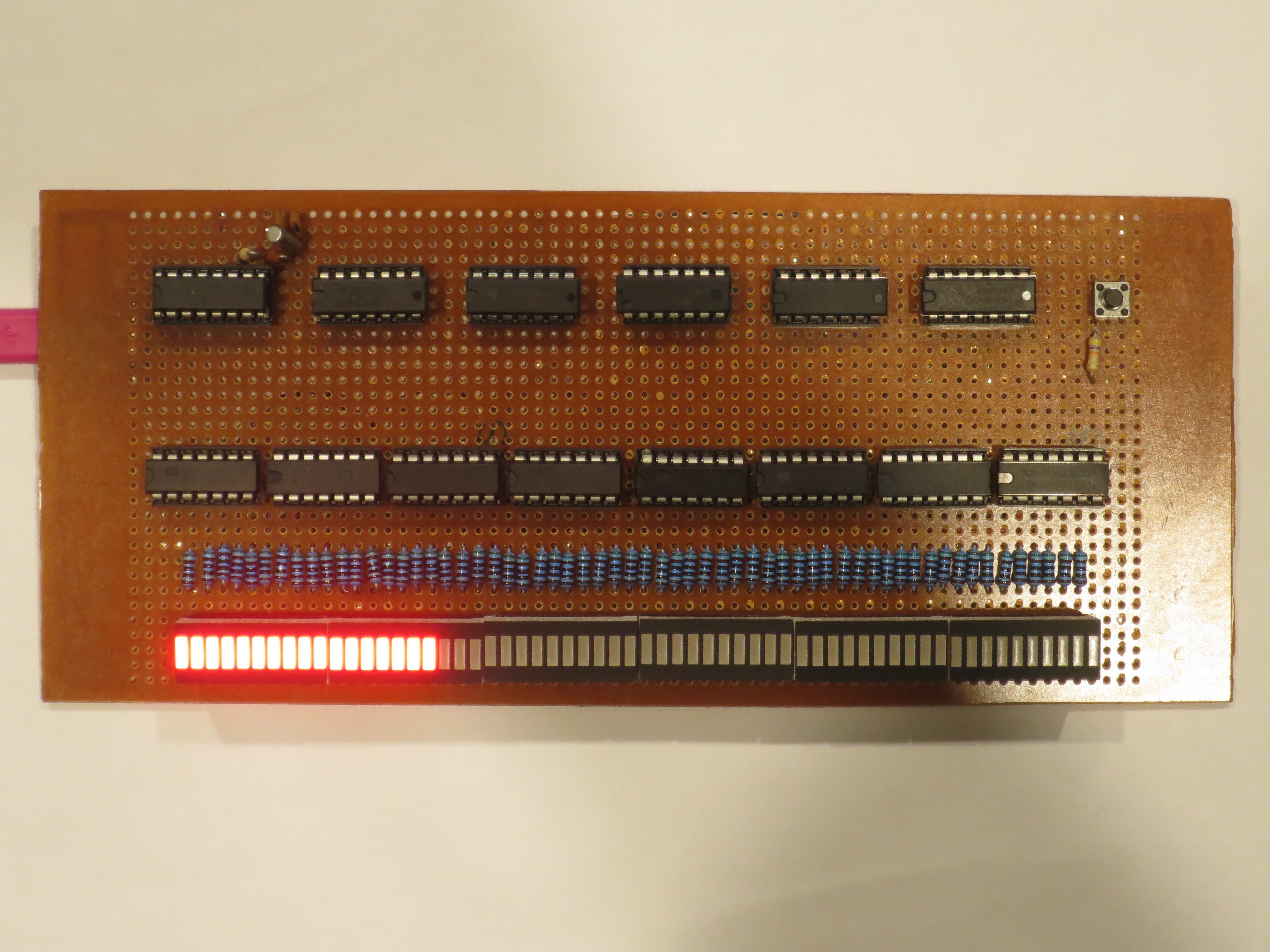
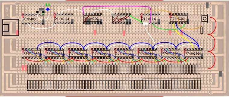
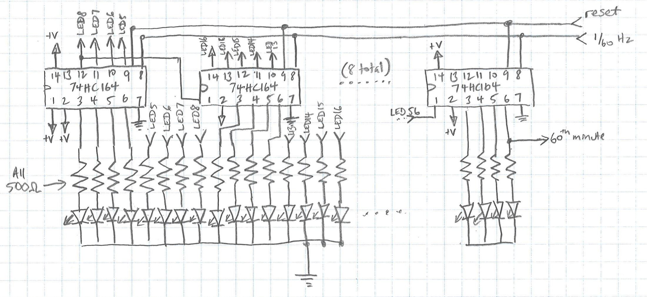
http://www.bowdenshobbycircuits.info/page5.htm#60clock.gif - Detailed description of clock that displays minutes on 60 LEDs. My main source of information in regards to the use of daisy chained 74HC164s

https://medium.com/@erikvanzijst/a-digital-quartz-clock-from-scratch-a80ec5e427 - Only found after I had finished, but an excellent write-up of a no-microcontroller digital clock. Has a similar but more elegant solution to setting the time than mine - would go that way if there is a next time.

IC datasheets:

CD4060 datasheet

CD4024 datasheet

74LS90 datasheet

74HC164 datasheet

74HC00 datasheet

CD4066 datasheet

LED Bargraph Clock.svg

"PCB layout" on protoboard using inkscape.

svg+xml - 5.67 MB - 01/12/2020 at 07:16

Download

  • 1 × Prototyping Board
  • 1 × 32.768 kHz crystal
  • 1 × 16 pin IC socket
  • 12 × 14 pin IC socket
  • 6 × 20 pin IC socket

View all 18 components

  • Done!

    trialexhill01/12/2020 at 07:31 0 comments

    Done! Working! Happy with that. I only made a few silly mistakes while soldering it up - I don't think I had to change the design or anything.

    Happy with how it works!

    The LEDs don't line up seamlessly, but that's OK, it actually makes it easier to read by making every 10 minutes slightly different.

    Underside looks OK. I could have been better with making the connections neater.

    There can be a bit of contact bounce when setting the time (especially when releasing the switch) but that's OK.

    I think I'm going to mount it on the wall of my cubicle at work.

  • "PCB" Layout

    trialexhill01/12/2020 at 07:28 0 comments

    Here's my "PCB" layout. I like to use prototyping board and point to point wiring, with a layout done in vector format using Inkscape.
     This then gets "flipped" to have a copper side view.

    I always end up making a few  changes on the fly.

  • Testing Out Time Setting

    trialexhill11/23/2019 at 08:31 0 comments

    Tested out the time setting function. The arduino is providing two frequencies, one per second and five per second. Both go into the 4066. The control pin for the one per second pulse is connected to a "voltage divider" with a switch on the low side. In the normal state, the button is not pushed, so the control pin for the one per second pulse is high, and the 4066 passes through the one per second pulse. The same control signal is also fed to the 74HC00 NAND. The other pin on the same NAND gate is connected to 5V. So in the normal state with no button push, the output of the NAND gate is low. This is connected to the control pin of the five per second pulse of the 4066. Because it's low, the 4066 gate blocks that signal.

    When the button is pushed, the control pin of the one per second is now low, and the control pin for the five per second is high. The 4066 then lets through the five per second signal. 

    The 4066 outputs for the one and five per second are connected together, and to an LED that therefore flashes at one per second normally, and five per second when the button is pushed. I'll use this set up to allow the minutes to be set. Pushing the button will interrupt the normal one per minute pulse, and allow though a faster pulse rate. I'm not sure what speed is appropriate - either one per second or two per second seem like good candidates.

  • 74LS164 testing

    trialexhill11/12/2019 at 10:40 0 comments

    I made up the minutes display section on a breadboard to make sure my plan would work. I used two '164s, two LED bar graph segments, and the '00 NAND gate. This is enough to prove the counting, daisychaining and resetting. I used my super old school arduino to provide power and a 1 pulse per second clock signal.

    After correcting a few wiring errors it all worked! Happy with that. Although these aren't the LED segments I'll be using in the final version, it seemed like the brightness was fine using 500ohm resistors.

View all 4 project logs

  • 1
    Stage 1 - 1Hz Timebase

    This section creates a 1Hz pulse output.

    The intent of the clock is to just display minutes only. Although I'm not actually displaying or keeping track of seconds, there is no such think as a 1/60Hz (0.166666Hz) crystal. It would be possible to create a 1/60Hz frequency output using a 555 timer and carefully chosen capacitors and resistors, but getting an accuracy acceptable for a clock would be impossible. It is better to go with a crystal and divide the frequency down.

    A 32768Hz crystal is connected to the inputs of a CD4060 IC. The IC divides the frequency by two on each successive input. For example the first output is Q4 (pin 7), so for a 32768Hz input, the output is 32768/(2^4)=2048Hz. 

    Unfortunately the last output is Q14, which gives 32768 / (2^14) = 2 Hz. Although I'm not actually displaying seconds on my clock, it would be nice to have a 1Hz frequency available, even just for ease of thinking about future diiding a once per second pulse to a once per minute pulse. 

    The 2Hz signal from the CD4060 is then passed to the input of a CD4024 IC. This IC again divides the frequency by 2 at each stage, giving a 1Hz signal on output Q1 (pin 12).

    Although these chips have similar functions, and it'd be nice to use just one type of IC, the CD4060 generates the output based on an external crystal/resonator, whereas the CD4024 needs an existing clock signal. 

    I've used these two ICs to create a 1Hz signal for a previous task. While building that project  I found that it was unreliable on a breadboard, but worked much more reliably when soldered to a prototyping board. For this project I will build this part of the circuit on the final board initially, as I'm confident in assembling it correctly. I can use the output to drive other new sections built on a breadboard.

    The values for the resistor and capacitor are probably not critical, but are what I've previously used. I'm not sure where I got them from originally, but they are similar to many other examples online. Pin 12 on the CD4060 is a reset pin, and should be grounded during normal use.

    BOM for this stage:

    • 1 x CD4060
    • 1 x CD4024
    • 1 x 32768Hz crystal
    • 2 x 22pF capacitors
    • 1 x 1Mohm resistor
    • 1 x 10Mohm resistor
    • 1 x 16 pin IC socket
    • 1 x 14 pin IC socket
  • 2
    Stage 2 - One pulse per minute

    Stage 1 results in a 1Hz (i.e. once per second) signal. This clock will display minutes, so the signal needs to be divided by 60 to get a 1/60Hz (once every sixty seconds or once per minute) signal.

    The first stage took advantage of frequency dividers that used binary powers to quickly reduce the frequency. Given this stage divides by 60, which is not a power of 2, the dividers need to use decade counters. A common part to do this is the 74LS90.

    The 74LS90 internally has two stages, a divide by two and a divide by five. The output of the first stage can be fed into the input of the second stage, to give a maximum of divide by 10. The outputs can be cleverly combined with the reset pins to give an output of any number between two and ten.

    To divide by 60, the two 74LS90 ICs are used. The first divides the input of the first stage by 10, giving an output of 1/10Hz. This is passed to the second 74LS90, which divides the signal by six to give the desired output of 1/60Hz or one per minute.

    In regards to the reset pin configuration, I don't have a great understanding of how to calculate which inputs and outputs are connected. To work it out I used the datasheet and this excellent site.

    BOM for this stage:

    • 2 x 74LS90
    • 2 x 14 pin IC socket
  • 3
    Stage 3 - Display Minutes

    This stage displays the minutes on 60 LEDs arranged as a bar graph.

    74HC164 serial-in, parallel-out shift registers are used. The shift register looks at it's inputs, and at every clock input, shifts all of the current values one over, looks at the current value of the input, and adds that value to the bottom of the pile. For this application, we start the hour with all low values, and every minute add one high value to the pile. So the input to the first 74HC164 is always high (the 74HC164 has two input pins [1 and 2] which are OR'd together, so we need both to be high). The 1 pulse per minute is applied to the clock pin, pin 8.

    When the clock is turned on, all values in the shift register are low, so all the LEDs are turned off. After one minute the clock pin changes from low to high. The 74HC164 reads the input pins as high, so changes the first output pin to high, and the first LED turns on. After one minute, the clock pin again changes from low to high, the 74HC164 moves the high value from the last minute to the second output, and again reads the input pins as high, making the first output high again. Now the first two LEDs are turned on.

    The 74HC164 has only eight outputs. The 74HC164 can be "daisy chained" - the last output of the one can become the input of the next. By doing this eight times, there are enough total outputs to control 60 LEDs.

    All of the clock pins of the 74HC164s are connected, so that they all change simultaneously.

    After one hour, all of the LEDs need to be turned off again to start counting a new hour. This is done but resetting the 74HC164s. The reset pin is pin 9, and it is reset when the pin is low. We have a "signal" when the hour occurs, i.e. the 60th output of the chain of 74HC164s, but this is a high signal. A NAND gate in a 74HC00 is used to invert the signal. The NAND gate takes two inputs, and outputs high if either of the inputs are low (and conversely a low when both inputs are high). One of the inputs is permanently held high, the other is connected to the 60th output. During the first 59 minutes, the 60th output is low, so the NAND gate output is high, and the 74HC164s operate as normal. When the 60th output goes high, both NAND gate inputs are high, so the NAND gate output goes low. The output is connected to all of the reset pins of the 74HC164s, so when the NAND gate goes low, all of the 74HC164s reset, and the whole process starts again.

    BOM for this stage:

    • 8 x 74HC164
    • 1 x 74HC00
    • 9 x 14 pin IC socket
    • 6 x 10 LED bar graph displays
    • 6 x 20 pin IC sockets

View all 5 instructions

Enjoy this project?

Share

Discussions

Mario Gianota wrote 01/19/2021 at 15:45 point

Cool project. I like it. I see you used the CD4060 to divide down the crystal frequency. Me too. I am kind of hoping I will get my CMOS Logic Clock finished before the end of February.

  Are you sure? yes | no

Ken Yap wrote 11/12/2019 at 11:25 point

There's another way to get your 1 Hz signal and save an additional IC, and that is to feed the 2 Hz signal into the divide by 2 stage of the 7490 first before the divide by 5. Then follow by a 7493 wired to divide by 12 so that you have a division factor of 120, giving 1/60 Hz, or 1/minute.

  Are you sure? yes | no

trialexhill wrote 11/13/2019 at 23:55 point

Iiiiiiiinteresting.

I guess that's something I should have worked out earlier, given the '90, '92 and '93 share a datasheet...

Now the question is should I use what I've got on hand, or save the IC as you suggest but have to go out and buy something else...

Thanks again!

  Are you sure? yes | no

Ken Yap wrote 11/14/2019 at 22:12 point

Well, I've been working on something using the same clock generator: https://hackaday.io/project/168157-ttl-binary-clock but with binary output.

  Are you sure? yes | no

Ken Yap wrote 10/28/2019 at 01:21 point

CD4060, nice. I'm sure it will be a good project.

You might like to take advantage of what I learnt about 32.768 kHz crystals in my related project: https://hackaday.io/project/167443-crystal-tester

  Are you sure? yes | no

trialexhill wrote 10/28/2019 at 01:34 point

Thanks for the comment. I agree with your comments that it is hard to get a CD4060 circuit working properly on a breadboard - I had the same thing on a previous clock project that had me scratching my head for a long time. 

On that project it looks like I used c_in = c_out = 22pF, Rf = 10Mohm, R = 1Mohm. Not sure where I got those values from, but they seemed to work. 

Thanks again.

  Are you sure? yes | no

Similar Projects

Does this project spark your interest?

Become a member to follow this project and never miss any updates