 Jared Sanson
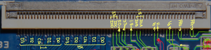 The connector provides two independent MIPI channels, each with 4 data pairs & 1 clock pair. The 5V rail is always powered, but the other rails can be individually sequenced and controlled by the MCU. The GPIOs can be used to control additional regulators or enable control signals on the display board. They are output only.
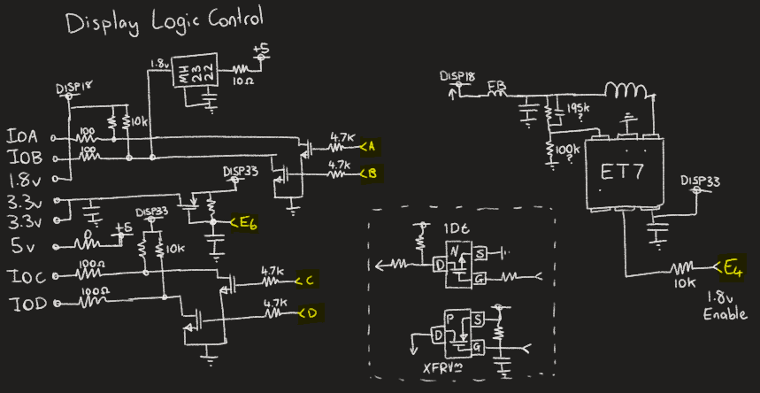
I do not know what chip "ET7" and "MH 23 22" are, but they are obviously some kind of buck regulator. A/B/C/D are the GPIO control signals from the MCU (output only).
E6 enables the 3.3v rail, and supplies the 1.8v regulator. IOC/D are powered even if this rail is not.
E4 enables the 1.8v rail to the display connector, but only if E6 is also enabled (for 3.3v). IOA/B are pulled-up to 1.8v if this is enabled.
The 5V rail is always powered.
I am not sure what the deal is with the chip at the top that is fed directly from +5v.
TFT Backlight Driver
For TFTs, there is a dedicated backlight driver:
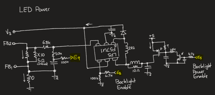 V3 is +V for the backlight, and either FB1/2 can probably be chosen for -V depending on the drive strength that is desired.
E9 is obviously an analog feedback signal to the MCU for controlling the drive current, E5 is the main supply enable, and E8 is probably a PWM control signal for defining the drive current.
OLED Bias Voltage
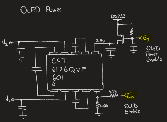
E7 enables the bias circuit.
E10 is probably a PWM drive signal for controlling display brightness.
On my board, the following signals come up in this order when it is powered on: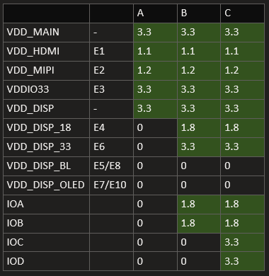 A: Slow Flashing
Blue LED / Initial power-up
A: Slow Flashing
Blue LED / Initial power-upB: Fast Flashing Blue LED
C: Green LED
You can see that on my board, the LED backlight & OLED bias supplies are never turned on. Instead the dsplay board has it's own regulators which are controlled by the IOA/B/C/D GPIOs.
Full connector pinout:
| Number | Net Name | Voltage | Breakout Net | Use | Description |
| 1 | FB1 | | | | Feedback 1 |
| 2 | FB1 | | | | Feedback 1 |
| 3 | - | | | | |
| 4 | - | | | | |
| 5 | FB2 | | | | Feedback 2 |
| 6 | FB2 | | | | Feedback 2 |
| 7 | - | | | | |
| 8 | V3 | | | | Backlight |
| 9 | V3 | | | | Backlight |
| 10 | V3 | | | | Backlight |
| 11 | - | | | | |
| 12 | GND | | | | |
| 13 | V1 | | | | OLED Bias (E7+E10 Ctrl) |
| 14 | V2 | | | | OLED Bias (E7+E10 Ctrl) |
| 15 | - | | | | |
| 16 | - | | | | |
| 17 | - | | | | |
| 18 | - | | | | |
| 19 | IOA | 1.8 | G | Right OLED Enable? | E4 Ctrl |
| 20 | IOB | 1.8 | F | Right OLED Enable? | E4 Ctrl or Always powered? |
| 21 | - | | | | |
| 22 | V_1.8 | 1.8 | E | 1.8v Supply | E4 Ctrl |
| 23 | - | | | | |
| 24 | V_3.3 | 3.3 | N | 3.3v Supply (1st) | E6 Ctrl |
| 25 | V_3.3 | 3.3 | N | 3.3v Supply (1st) | E6 Ctrl |
| 26 | V_5.0 | 5.0 | | | USB VIN, Always powered |
| 27 | IOC | 3.3 | L | Enable OLED Bias (2nd) | Always powered |
| 28 | IOD | 3.3 | M | Enable 2.8v Supply (1st) | Always powered |
| 29 | - | | | | |
| 30 | GND | | | | |
| 31 | DSI0_D0 | | D | | |
| 32 | DSI0_D0 | | D | | |
| 33 | GND | | | | |
| 34 | DSI0_D1 | | | | |
| 35 | DSI0_D1 | | | | |
| 36 | GND | | | | |
| 37 | DSI0_C | | C | | |
| 38 | DSI0_C | | C | | |
| 39 | GND | | | | |
| 40 | DSI0_D2 | | | | |
| 41 | DSI0_D2 | | | | |
| 42 | GND | | | | |
| 43 | DSI0_D3 | | | | |
| 44 | DSI0_D3 | | | | |
| 45 | GND | | | | |
| 46 | DSI1_D0 | | B | | |
| 47 | DSI1_D0 | | B | | |
| 48 | GND | | | | |
| 49 | DSI1_D1 | | | | |
| 50 | DSI1_D1 | | | | |
| 51 | GND | | | | |
| 52 | DSI1_C | | A | | |
| 53 | DSI1_C | | A | | |
| 54 | GND | | | | |
| 55 | DSI1_D2 | | | | |
| 56 | DSI1_D2 | | | | |
| 57 | GND | | | | |
| 58 | DSI1_D3 | | | | |
| 59 | DSI1_D3 | | | | |
| 60 | GND | | | | |
Discussions
Become a Hackaday.io Member
Create an account to leave a comment. Already have an account? Log In.