 Matthew James Bellafaire
I want to start off this log by saying that the Revision 3 board works fine, it accomplishes the basic goals of the project and performs its function well enough. With that said however, I've identified a couple of issues that I’m going to fix in a new revision soon enough here.
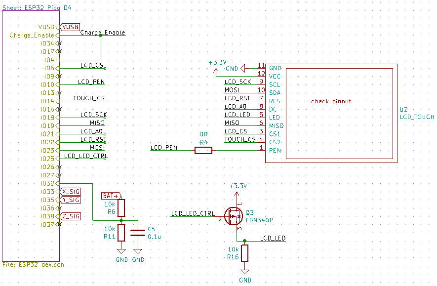
I've annotated the current schematic with the changes that I'm currently planning on implementing but I want to put them here along with some extra information and some planned changes. As of right now the change list looks like this:
- change MCP73811T charging current to 200mA using prog pin - remove PMOS for LCD backlight control - configure power-in circuitry so the device can run directly from USB power when charging - battery voltage sensing solution to something external to micro controller - Replace MAX9065 with new battery monitor (or disconnect as a undervoltage shutoff) - Implement Power-off functionality for accelerometer and LCD. power drain of these devices in standby is too high - Ensure that any touch input interrupt is attached to an RTC GPIO pin so that the ESP32 doesn't have to poll the pin
The purpose of this log is primarily to document some of the changes that I'm planning on making and the mistakes that were made with the current design.
- change MCP73811T charging current to 200mA using prog pin
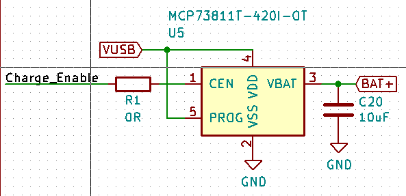
This one I should have
caught. In the battery charging sub-circuit I configured the prog pin to VUSB
for simplicity. The problem with this is that the charge current for the
battery cannot be reconfigured, in the current circuit configuration the
MCP73811T charges the battery at a blistering fast 500mA which on top of not
being good for the battery also creates trouble with the USB connection (USB
doesn't exactly like 500mA being drawn while communication is happening). The
result of this configuration is that the smartwatch will not communicate over
USB while the charge enable pin is reading a high voltage. Originally, I
planned for this and configured one of the CBUS pins on the UART bridge to
control the battery controller, this solution kind of works but occasionally
it will cause problems and result in the device not connecting properly to the
PC.
- remove PMOS for LCD backlight control
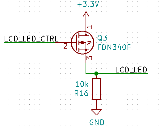
The board was designed before I received the LCD modules that were chosen to be used in it. The result is that I had to infer the pin functions from the Bangood page (because you know, tons of documentation there). I was under the mistaken impression that the LED control pin was the anode of the LED, this appears to not be the case and the LCD module has its own internal switching circuitry. The result is that this entire sub circuit is redundant and LCD_LED_CTRL can connect directly to LCD_LED.
- configure power-in circuitry so the device can run directly from USB power when charging
Currently the entire circuit is connected to the positive terminal of the battery, even when charging power is being drawn from the battery (and the battery charging IC). While this doesn't cause any immediate problems that I've observed it is worth fixing.
- battery voltage sensing solution to something external to micro controller - Replace MAX9065 with new battery monitor (or disconnect as a undervoltage shutoff)
These are more-or-less the same thing, currently my battery management solution is to use a MAX9065 window comparator to automatically shut off the LDO that powers the ESP32 circuitry. The result of this is that the MAX9065 operates essentially separate from everything and if the battery voltage is too low or too high the entire smartwatch cannot function at all. In addition to this the current battery sensing solution simply uses the ADC of the ESP32 which can only approximate the battery voltage (and not very well). In the next revision I plan to choose a more complete battery management solution (Next log or two may cover how I'm going about selecting the battery management chip).
- Implement Power-off functionality for accelerometer and LCD. power drain of these devices in standby is too high
Everything draws power in a circuit, I have never attempted any design where power usage is a significant concern (all the more reason I enjoy this project) so I was somewhat blindsided by this one. Although the ESP32 can be put into deep sleep to conserve a significant amount of power the LCD and accelerometer remain active and drawing power. Currently there is no reason for the LCD controller to remain active while the ESP32 is in deep sleep and so the LCD itself should be disconnected from power to prevent the power draw.
- Ensure that any touch
input interrupt is attached to a RTC GPIO pin so that the ESP32 doesn't have to
poll the pin
Finally, the LCD has a PEN pin which indicates when the touch screen is being touched, currently it is connected to the ESP32P through IO10. The result of this placement of the pin is that the pin must be polled by the microcontroller by waking up from deep sleep. The ESP32 ULP supports external wakeups on specific pins, using these external wakeups would be far more efficient for my purposes.
As a final remark, I may switch the design from the ESP32 D4 Pico to the ESP32 WROOM or similar modular solution. While the Pico is fantastic in terms of size it is difficult to work with, in addition to this I know next to nothing about RF design and had a lot of difficulty selecting and laying out an antenna on this board. While the current smartwatch WIFI works better than expected I feel uneasy about using it without knowing more about any stray signals it may be throwing off. Switching to a pre-packaged module should save a significant amount of trouble but presents its own layout challenges given the limited board space of this project.
Overall, I fell into a lot of traps with this project and plan to take things slower going forward. I never really look at failures in my projects as something bad, generally it’s the failures that teach me the most and this project overall has pushed me to learn quite a bit. I plan to make more regular logs about the progress and maybe even sub circuits of the design just for the purposes of documenting what's happening with this design.
Either way, that's all I had to write about this, see you in the next log!
Discussions
Become a Hackaday.io Member
Create an account to leave a comment. Already have an account? Log In.