A non-isolated buck is simple and that enhances durability and efficiency. But the details of how it is implemented can present challenges. For this project there are three:
- Output relay (SSR) and non-isolation between PV & battery
- Low-side synchronous control
- Current sensing
Output Relay. The problem with any design that must deal with external voltages present on both its input and output is preventing current reversal - e.g. the flow of current from output to input. In isolated designs this is generally not a problem. In non-isolated designs the easy solution is a blocking diode; but these introduce losses. In this design, 100W at 14V is 7.14A. The best schottky might get close to a Vf of 400mV but that is still (7.14 * 0.4) = 2.85W. Paralleling doesn't help, it just distributes the loss over more components.
An SSR (Solid State Relay) solves the efficiency problem. The custom design in this unit has an on resistance ~ 5.3mΩ, so the loss from the above example would be (7.14^2 * 0.0053) = 270mW. The problem with an SSR is that it cannot be left on when the buck is not running: battery voltage would forward bias the high-side MOSFET body diode. A secondary problem could be turning the buck into a boost (again, in reverse) depending on how long the low-side MOSFET is turned on: too long and the inductor will charge and attempt to discharge its energy when the low-side is turned off.
The design avoids these deficiencies thru firmware control and leveraging the best of both worlds. At low loads the SSR is kept off and output current flows thru the SSR's body diode. At higher loads the SSR is on. Since there's no output current sense, PV current is used as a proxy.
Low side control. Low side synchronous control is best done in hardware by sensing the flyback current. This design doesn't accommodate, so on-time must be estimated based on operating conditions. Like the output relay, the goal is to minimize losses by having the majority of current flow thru the MOSFET and not its body diode. I derived a few approaches to this problem in my Synchronous Buck Control project.
A somewhat simpler, binary approach is used here. At light loads (based on PV current) a minimal on-time is maintained (few hundreds nS) that is enough to maintain bootstrap capacitor charge but not long enough for current reversal. At higher loads, approximately when the inductor is expected to be in continuous conduction, the on-time is increased to a value slightly higher than the longest on-time possible under any load conditions. In effect, it removes the restriction from the hardware control loop and allows it to determine on-time based on duty cycle.
Current sensing. Actually, this isn't a challenge for the current design but possibly one for future, higher power designs. The unidirectional current transformer is a super-clean and simple method to sense current in a switching supply. Here's a 'raw' sample taken from the prototype running close to max load. The probe is a passive Tek P6563A 20x (9.5MΩ impedance, 4.5pF):
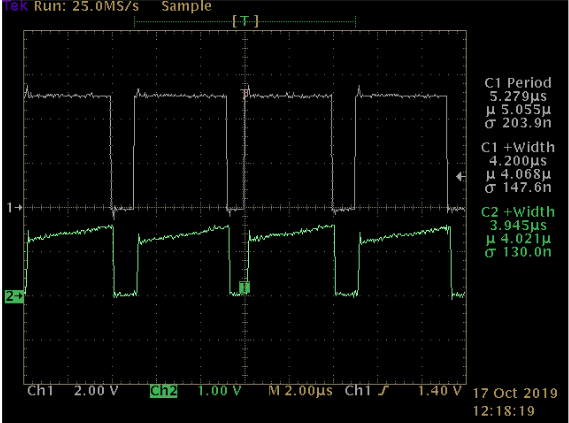
This was probed at the MCU's pin. There is no conditioning circuit; just a buffer resistor between the sense circuit's output and the MCU.
This has a big impact on the current mode control method. To ensure loop stability and minimize jitter the S/N ratio of the current signal seen by the comparator (comparing to the slope compensation ramp) must be good. Other methods usually involve some type of shunt resistor and will require active conditioning to remove the noise without distorting the signal. This is why most modern current mode supplies employ a monolithic control chip with all of that stuff built in.
The problem with unidirectional current transformers is that the core must be reset on each cycle and that requires time. Running at 200kHz, as this design does, with a maximum on-time of 4.6uS allows only 400nS for this to happen. Resetting the core is basically balancing the volt-seconds, so to do so in less than that amount of time at max. load will see a voltage across the transformer of ~ 108 volts. Boosting the design to handle peak switching currents of 20A would see voltages exceeding 200V. This isn't necessarily a problem as long as the correct components & layout are used.
Discussions
Become a Hackaday.io Member
Create an account to leave a comment. Already have an account? Log In.