 hamster
VFD Tubes!
It all started about a year ago. I wanted to make a project based on some Nixie tubes, like everyone else, but was turned off by the high cost of tubes and the high voltage driving requirements. Digging around, i found VFD tubes, but all the ones I found were just digits. Then one day digging around on eBay, I found some IV-17 tubes, which are alphanumeric!
I bought the tubes, then they went onto my parts shelf waiting for the right project to be put into.
IV-17
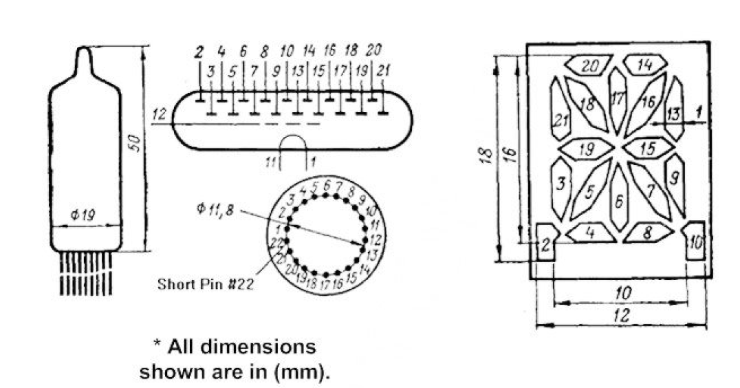
The tube itself is a fairly standard 16 element alphanumeric, with a dot on each side of the tube. Furthermore, the driving characteristics are much more friendly:
Filament
- 2.4V, 47mA
Grid and anode
- Nominal voltage - 25V
- Maximal voltage - 30V
- Pulse voltage - 50-70V
- Segment current - 2.5mA
- Grid current - 3-6mA
Ok, well - 25V is not really battery level, but it's manageable. The next question became, how do I get 25V?
I researched at length for a power supply, and found nothing really concrete on how to go about it. Everyone had a different idea of how to get the voltage. In the end, I borrowed most of the design from adafruit Ice Tube Clock for the switcher.
Pros
- Minimal part count
- Easy to change the operating point in software
- Easy to change brightness and drive level in software
Cons
- No voltage readback
- No protection from a software failure latching the MOSFET on
Eh... I think it will do. Take a look at the schematic snippet:
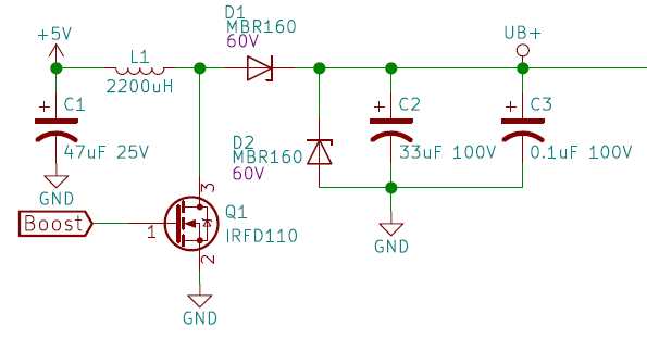
Like with all boost switch mode power supplies, the magic is in the inductor and diode. Let's walk through the theory of operation:
- 5V is applied to C1. We're going to be gulping power from this cap, so this helps provide a tank of energy
- The controller applies drive to Q1, and Q1 conducts
- 5V is placed across the inductor L1. The circuit is now shorted across L1, so we need to let go before L1 fully quenches
- Q1 drive is released. The inductor wants to maintain current across it, so as the magnetic field collapses, it generates a voltage spike.
- D1 steers this voltage spike into the C2/C3 tank and prevents backflow of the voltage to the 5V rail
- High voltage is now available at UB+
- D2 will begin to conduct around 60V, limiting the output voltage of the supply (a caution here, below)
The harder we drive the duty cycle of Q1, the more power we get out of this guy, to a limit. You have to tune L1 based on your drive frequency, the input voltage and your desired output voltage. You also need to consider the power rating of L1. The current across L1 can be quite a bit higher than output current of the supply. In this circuit, I went with a 1A rated inductor, and a fairly generic value of 2200uH. In all honesty, I could really stand to come back and re-design this supply with a couple of changes:
- L1 was originally picked for about 30khz drive, but the attiny1616 is only giving me 10khz
- D2 was an OK idea to prevent tube damage, but in reality the 1A part I picked can go up in smoke if I drive this supply too hard (!)
- A drive lockout for Q1 to prevent latchup and a short circuit might be a good idea. Or a resistor as a one-time smoking fuse..
- Voltage feedback is possible with the microcontroller I picked, which might be nice
Finally, do note that if you don't have a load on the output of your switcher, the output voltage will keep climbing until something blows up. I overlooked this in the design - I ended up bodging on a 4.7k resistor across the output to prevent the supply from running away. Once you turn on the tube elements, that's enough load to keep things in check, however.
Filament driver
There are a lot of options for driving the filament. It's fairly low voltage at 2.5v, but it's going to eat 47mA. That's a fairly big hit for driving this tube when everything else is much lower power (but higher voltage).
Technically, you should drive the filament with an AC square wave. It is likely the...
Read more »

 John Duffy
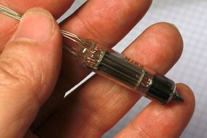
 Yann Guidon / YGDES
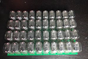
 robert.c.baruch
 Paul Andrews
I'd like to make a IV3a VFD Tube MilliAmp meter for my CO2 Laser. Idk how to tho.. lol