 hamster
VFD Tubes!
It all started about a year ago. I wanted to make a project based on some Nixie tubes, like everyone else, but was turned off by the high cost of tubes and the high voltage driving requirements. Digging around, i found VFD tubes, but all the ones I found were just digits. Then one day digging around on eBay, I found some IV-17 tubes, which are alphanumeric!
I bought the tubes, then they went onto my parts shelf waiting for the right project to be put into.
IV-17
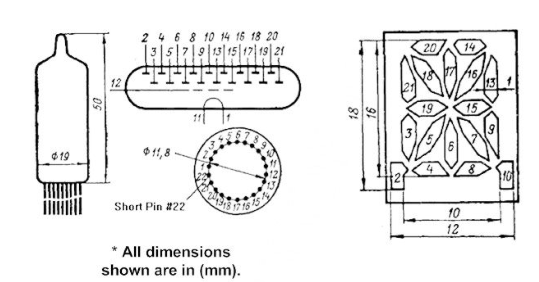
The tube itself is a fairly standard 16 element alphanumeric, with a dot on each side of the tube. Furthermore, the driving characteristics are much more friendly:
Filament
- 2.4V, 47mA
Grid and anode
- Nominal voltage - 25V
- Maximal voltage - 30V
- Pulse voltage - 50-70V
- Segment current - 2.5mA
- Grid current - 3-6mA
Ok, well - 25V is not really battery level, but it's manageable. The next question became, how do I get 25V?
I researched at length for a power supply, and found nothing really concrete on how to go about it. Everyone had a different idea of how to get the voltage. In the end, I borrowed most of the design from adafruit Ice Tube Clock for the switcher.
Pros
- Minimal part count
- Easy to change the operating point in software
- Easy to change brightness and drive level in software
Cons
- No voltage readback
- No protection from a software failure latching the MOSFET on
Eh... I think it will do. Take a look at the schematic snippet:
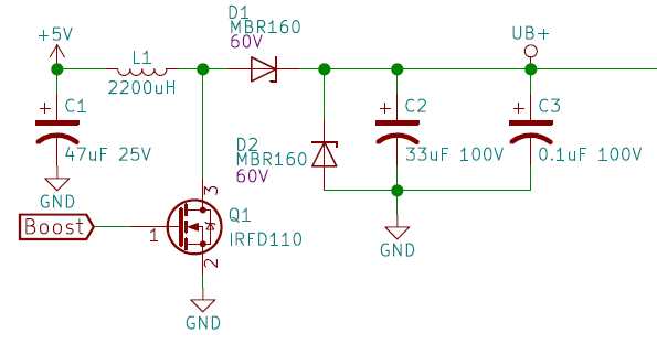
Like with all boost switch mode power supplies, the magic is in the inductor and diode. Let's walk through the theory of operation:
- 5V is applied to C1. We're going to be gulping power from this cap, so this helps provide a tank of energy
- The controller applies drive to Q1, and Q1 conducts
- 5V is placed across the inductor L1. The circuit is now shorted across L1, so we need to let go before L1 fully quenches
- Q1 drive is released. The inductor wants to maintain current across it, so as the magnetic field collapses, it generates a voltage spike.
- D1 steers this voltage spike into the C2/C3 tank and prevents backflow of the voltage to the 5V rail
- High voltage is now available at UB+
- D2 will begin to conduct around 60V, limiting the output voltage of the supply (a caution here, below)
The harder we drive the duty cycle of Q1, the more power we get out of this guy, to a limit. You have to tune L1 based on your drive frequency, the input voltage and your desired output voltage. You also need to consider the power rating of L1. The current across L1 can be quite a bit higher than output current of the supply. In this circuit, I went with a 1A rated inductor, and a fairly generic value of 2200uH. In all honesty, I could really stand to come back and re-design this supply with a couple of changes:
- L1 was originally picked for about 30khz drive, but the attiny1616 is only giving me 10khz
- D2 was an OK idea to prevent tube damage, but in reality the 1A part I picked can go up in smoke if I drive this supply too hard (!)
- A drive lockout for Q1 to prevent latchup and a short circuit might be a good idea. Or a resistor as a one-time smoking fuse..
- Voltage feedback is possible with the microcontroller I picked, which might be nice
Finally, do note that if you don't have a load on the output of your switcher, the output voltage will keep climbing until something blows up. I overlooked this in the design - I ended up bodging on a 4.7k resistor across the output to prevent the supply from running away. Once you turn on the tube elements, that's enough load to keep things in check, however.
Filament driver
There are a lot of options for driving the filament. It's fairly low voltage at 2.5v, but it's going to eat 47mA. That's a fairly big hit for driving this tube when everything else is much lower power (but higher voltage).
Technically, you should drive the filament with an AC square wave. It is likely the better thing to do for the long run on your tube, and especially for larger, multi-element tubes it will make sure you get even brightness across the tube. A good chip for this is the LM9022, which was designed just for this application. Bad news: it is no longer made. However, they can still be had for less than a buck a chip. You either need to drive it with a square wave, or hook up a bunch of passives to self-oscillate. It's very sensitive to your part layout. I tried using one, but I found it pretty power hungry.
Ultimately, I went with using a 68 ohm resistor across the ~5V DC supply. Brightness is even across this small tube, and it's 'only' consuming about 30mA.
Segment Selection
The segments need to be driven with your new-found high voltage. There are various options out there. Some people opt for a series of high-side drivers with bipolar transistors and MOSFETs, driving them either directly or with a BCD logic chip. However, there is a purpose-made chip out there that is just perfect for our needs. That chip is the HV5812 20 channel VFD anode driver. Capable of switching up to 80V, with a simple SPI interface and the ability to daisychain multiple chips, it makes this part of the project pretty easy.
The SPI drive is simple - you feed it 3 bytes. The chip uses 20 bits of the 24 bits to set the 20 outputs either high or low, and throws away the remaining 4 bytes. All you need to do in your microcontroller is build a table of character to byte value and feed the chip with the data.
In my design, I also put the grid drive as a channel, although I am always driving it active. This was just to make some wiring easy - you'd likely just want to set it to always be connected to the HVPS.
The HV5812 can be had in DIP, wide body SOIC or even PLCC. I went with SOIC as that was all I could fit.
Tube Mounting
I see a lot of boards made that make all the pads for the tube as castellated half-vias. I'd love to do that myself, but the fab cost penalty for doing this was just not worth it to me. Instead, I came up with a different plan. I would straighten out the leads on a fresh tube, then go around cutting each lead slightly shorter than the next. This allowed me to easily control getting the leads into the holes and into place. It was simple enough that I have no plans to go castellated.
Board Design
One of the main elements of the TubeCube is the cube form-factor.
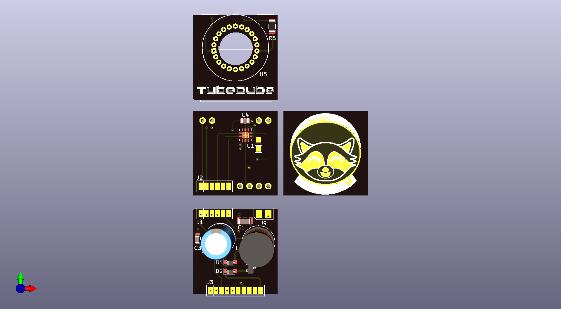
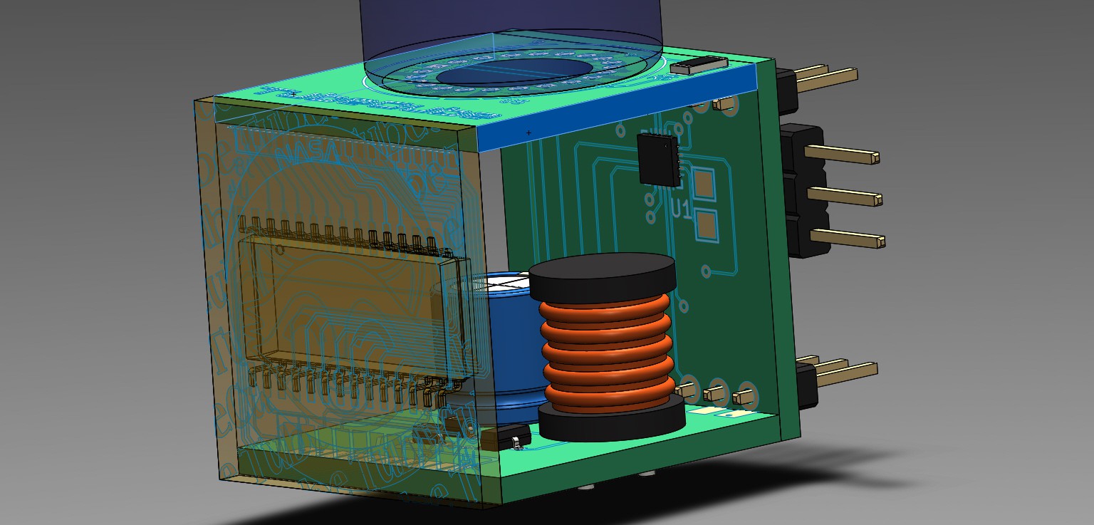
I didn't want a bunch of connectors or vias at the corners, but it also needed to be hand assembled. To accomplish this I built the boards so that they would stack into a cube, with some exposed pads at each inside corner. I could then reach inside with my iron and place a filet of solder to both mechanically hold the boards in place, as well as electrically conduct the signals around the inside of the unit.
It ended up looking great, but assembly is... challenging. I'm an idiot savant when it comes to soldering, so I pulled it off, but I'm not sure I would recommend it to anyone that finds soldering a chore.
Minibadge
The tubes plug into a Saintcon minibadge socket. It's a simple format that allows for about 0.8inch square addon badges. I've kind of bastardized this standard to make this thing work, hah.
Daisy Chain
The other aspect of the tubes was that I wanted to be able to chain them together. It's hard to read strings off a single tube after all. To make this work, I have a set of pins and sockets off the left and right sides of the back board. One side is UART RX, the other is UART TX.
At boot time, each digit sends out a 'magic' byte of 0x23. Each digit is also listening for this byte to come in. If a digit gets the byte, it knows it is a slave and just waits for data to come in. If a digit does not get the byte, it assumes it is the master after about a second, and starts clocking out a random string from the table of strings in the firmware.
Baud rate is 9600 baud, mostly so that noise from the power supply prevents getting trash characters.
Further, if a tube gets a valid char while it is running, even if it is the master, it goes into slave mode until the chip reboots, so you can stack on another tube or hook up a computer at any time.
To push the data out, each tube takes the char from the serial port and displays it on the tube. Once it gets another char, it pushes the currently displayed char out its serial port, and then displays the new char. This push/shove design makes it easy to scroll text across the tubes.
I put the RX and TX on the wrong sides in this version and had to make a bodge wire change on every unit to make them work.
Art
The front of the TubeCube has some PCB art. I'll have an article on making PCB art at some point in the future. For the time being, enjoy my talk from Saintcon about making pretty PCBs.
For Sale?
I ended up making 8 tubes for Saintcon - 4 of them were on my badge, and I ended up giving away a few of the other ones. I'm debating doing another rev and putting them on Tindie - but the build is involved and I worry that the price I would want to charge would not be something people would want to pay, unless I just wanted my time to be 'free'. Tell me what you think about this.