 A. Noniem ⚙
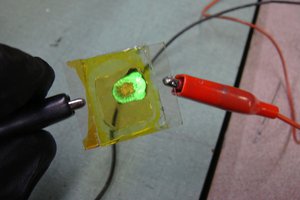
I had some fun modifying a Haloween mask.
The result:
Checkout the instructions to modify your own.
Everyone is busy but when joining my daughters this year in the Haloween walk I wanted something nice, special and easy to make.
Already have an account? Log in.
To make the experience fit your profile, pick a username and tell us what interests you.
I had some fun modifying a Haloween mask.
The result:
Checkout the instructions to modify your own.
Scary_Mask.inoUse Pin 8 for the NeoPixelsino - 2.72 kB - 11/02/2019 at 08:03 |
|
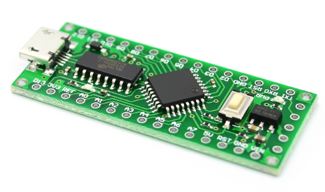
Remove the AMS1117 from the Arduino board it is the Voltage regulator which dissipates heat for voltage reduction.
We use a buck converter which takes less power.
In this case it's on the right side of the board.
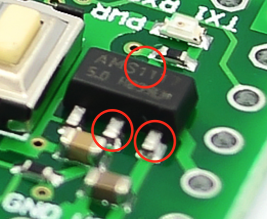
There are 4 pads on the board that will need to be "connected" in order for the board to work without this regulator. The 3 lower pads you can see connected to the AMS1117.
The center and right pad should be connected to each other and to the top pad. (invisible in the above image) Use a thin wire to accomplish this.
Dissipating heat is very bad for efficient power consumption.
To lower the consumption we will use a Buck converter; actually a combination of a buck (Stepping down) and boost (Stepping up) converter that focuses on 5v output.
They are bigger and more expensive but enable us to select a power source ranging from a 3v CR2032 cell to a 9v block battery.
If you want to know the workings of such a device check this youtube video:
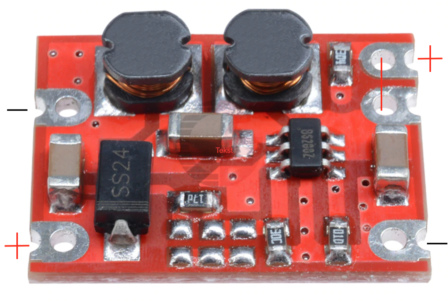
To continue; this is our Buck / Boost converter:
The left side of this image will connect to the Arduino (will get to that in a minute)
The right side of this image you will need to connect to the Power connector (+ to red - to black)
NOTE: Make sure to bridge (connect) the two connectors on the right side that are close to each other (One of the Pin's is to "ENABLE" the buck converter).
Tip: Alternatively you can attach a on-off switch on this connector.
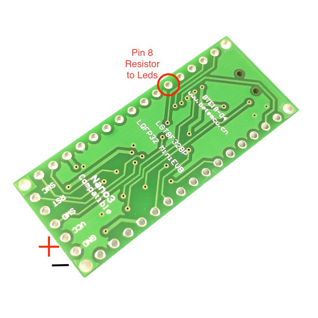
Now to the left side of the buck converter.
Connect the + wire to the VCC pin
Connect the - wire to the GND pin
A resistor has no polarity so just make sure it is positioned on the top side of the board so your back side of the PCB remains nice and smooth. (Easier for attaching / piggybacking)
Make sure to isolate the wire for it not to touch any components on the board.
I usually use some shrinking tube to cover and insulate the resistor.
Heat it for it to make the tube shrink.

 Ian Hanschen
 Lutetium
 Cobinson Rrusoe
 Tyler Anderson