There have been a number of digital logic projects that use relays. Most relay logic I've seen relies heavily on double-throw (form C) relays. I'm interested in circuits that use the simpler single-throw kind of relay.
SPST relays (1 form A) have a number of advantages. They're the simplest, cheapest, and generally the most reliable kind of relay. Also, most reed relays are SPST-NO relays, and reed relays also have some advantages for logic.
So, what can be built with just SPST relays?
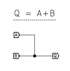
 Q is 1 only when A and B are both 0.
  When A is low, Q is pulled up to supply through R. When A goes high, Q is shorted to ground and goes low.
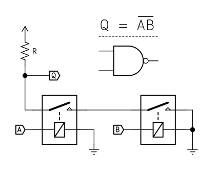 As well as NOR:
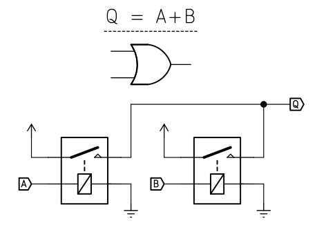
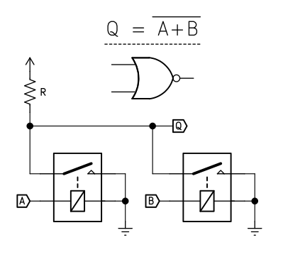


 Ted Yapo
 Yann Guidon / YGDES
 kamalkedin123
Mechanical is fun, but transmissions gates are worth at least being aware of.
Dual SPST, 3 Ohms when closed, 4.5nS to switch, 250pS to propagate.
ti.com/lit/ds/symlink/sn74cbt3306c.pdf
Provides no easy way to fake a diode bridge XOR across the coil though.
DPQT like 74CBT3253 provide a straighforward way to fake that bridge.
More throws than you were after, but no obligation to connect all of them.