 Benjamin Prescher
First, the brake documentation had to be procured and spotted - a Magtrol HD 510 - 8NA. The brake provides a TTL output for speed detection and measuring bridge outputs for torque detection. A small half-bridge circuit with active freewheel provides the braking energy. Likewise, the excitation current is measured and monitored. The brake requires various voltages such as +/- 24V, +/- 12V and 5V. Among other things, these are provided by a buck converter TPS5410 and DC / DC power supplies IA24xx. Things such as reverse polarity protection of the patch cord or a fuse link can also be taken into account, as well as I2C port expansion and level conversion for connecting a RepRap 2004 display.
0%
0%
MAGTROL Dynamometer control
New life for an old Magtrol Dynamometer! Create a controller card and run software tasks.
Become a Hackaday.io member
Already have an account? Log in.
Just one more thing
To make the experience fit your profile, pick a username and tell us what interests you.
Pick an awesome username
hackaday.io/
Your profile's URL: hackaday.io/username. Max 25 alphanumeric characters.
Pick a few interests
Projects that share your interests
People that share your interests


 jipe_rey
 Dan Sheadel
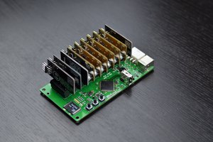
 plugg.ee Labs
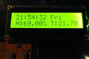
 bobnet