 Chris.deerleg
figure out the schematic for a PCB compatible to BLHeli32 firmware
The image above shows the pictures used to figure out the pinning
- Top side to see the components
- Top side with bight flash to see the traces
- Top side with hand colored traces
- Top side with some notes from datasheets
- Bottom side to see the components
- Mirror bottom with bight flash to see the trace
- Bottom side with hand colored traces
- Bottom side with some notes from datasheets
- The finish schematic
Second Step
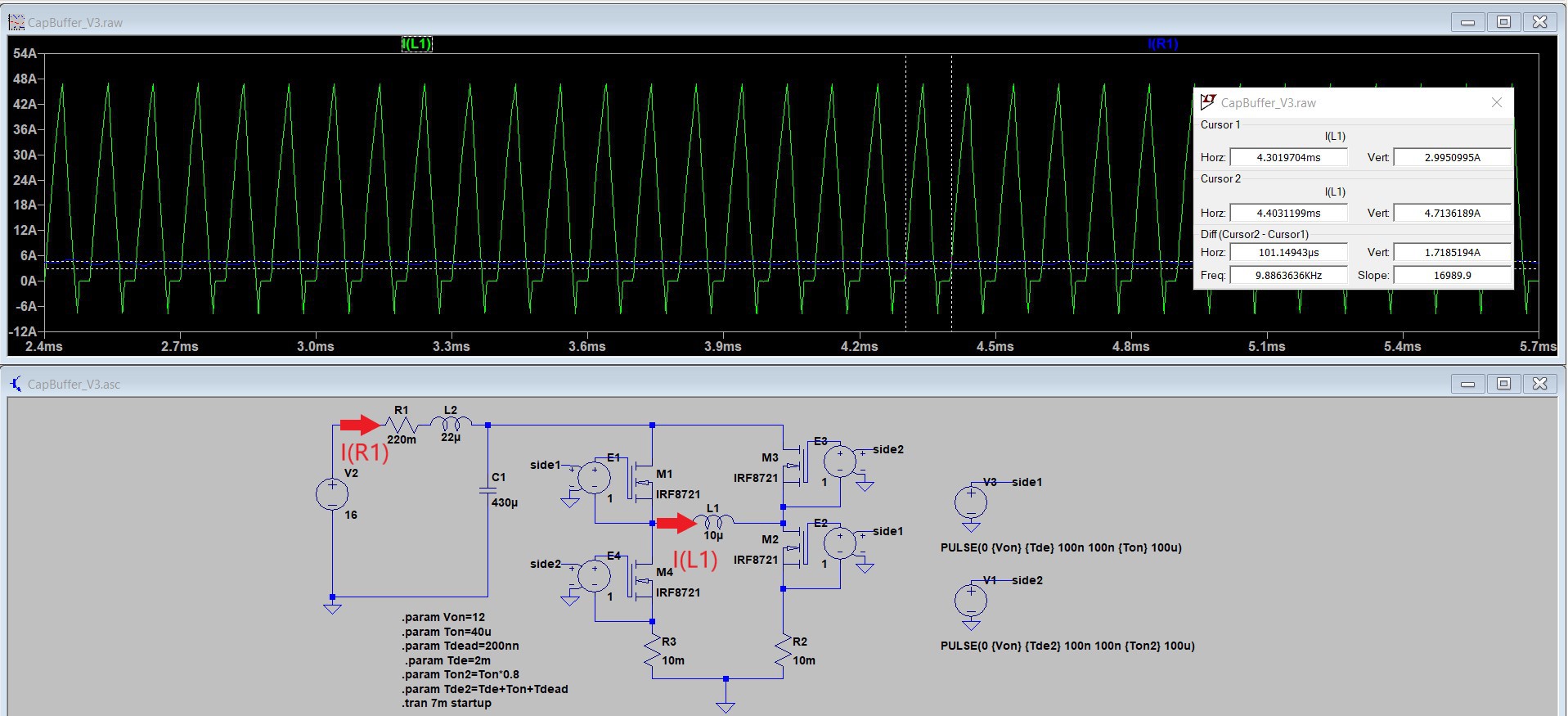
The image above shows the a H-Bridge simulation with a single motor winding and the buffer circuit. The current in to the buffer circuit is shown in blue I(R1) and about 4.7A. At the same time the green current I(L1) in the motor winding is up to 45A. The inductance L2 (22µH) and the capacitor C1 430µF is needed to reduce the ripple current I(R1) to about 1.7A. The resistor R1 limits the current at startup when the capacitor is empty.
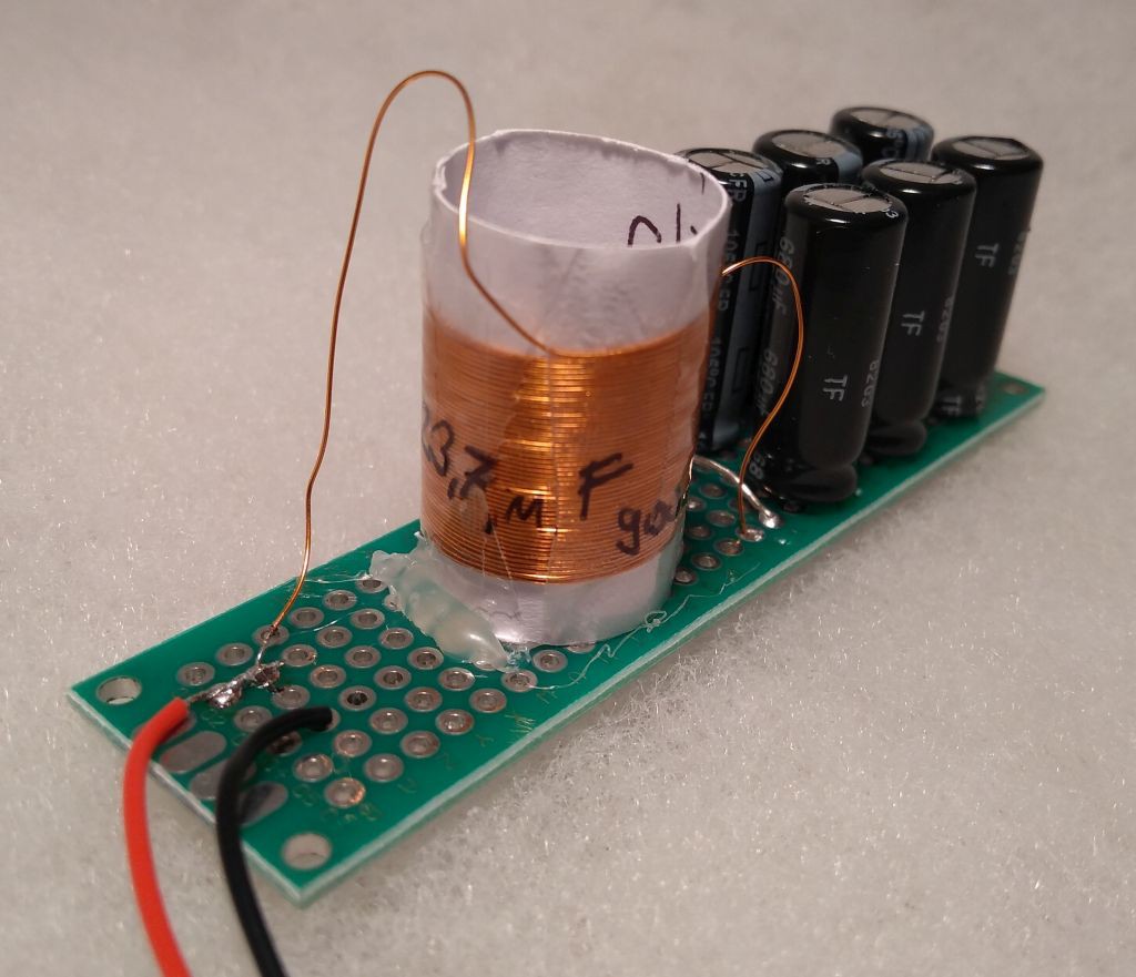
On the image above is the prototype of the buffer circuit shown. The coil has 23µH and consist of 45 winding of 0.3mm wire with a coil diameter of 15mm. I used 6 x 680µF / 25V low ESR electrolytic capacitor in parallel. I used these big capacitor because the electrolytic capacitors have to provide the ripple current of the motor winding with about 45A. The current rating of on capacitor is 1.7A therefore all 6 in parallel can sustain 10.2A. I hope that with 4 time overload the capacitors will not be too hot.
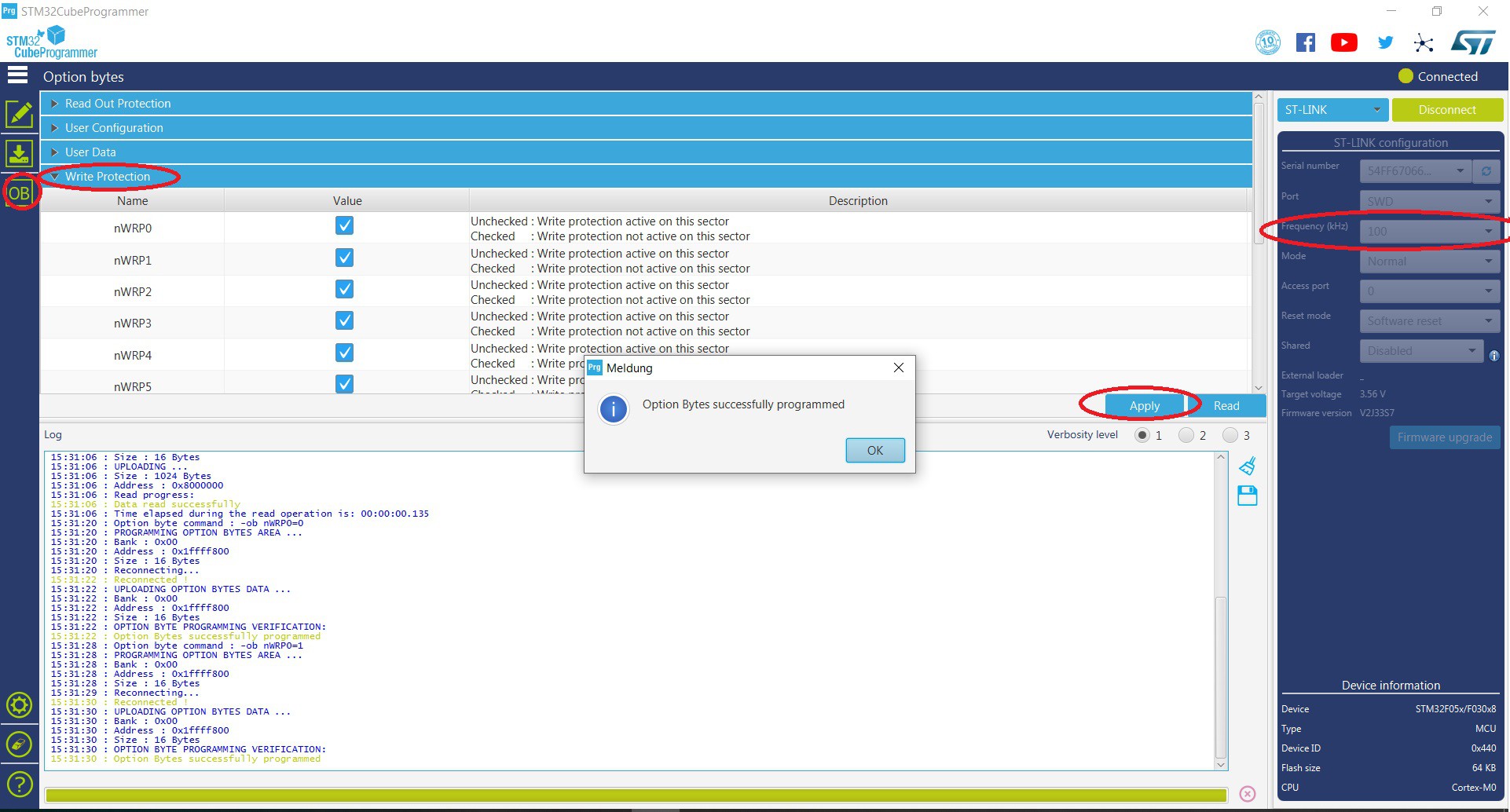
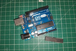
Third Step

"Hello World" the LED works. For further detail see the log
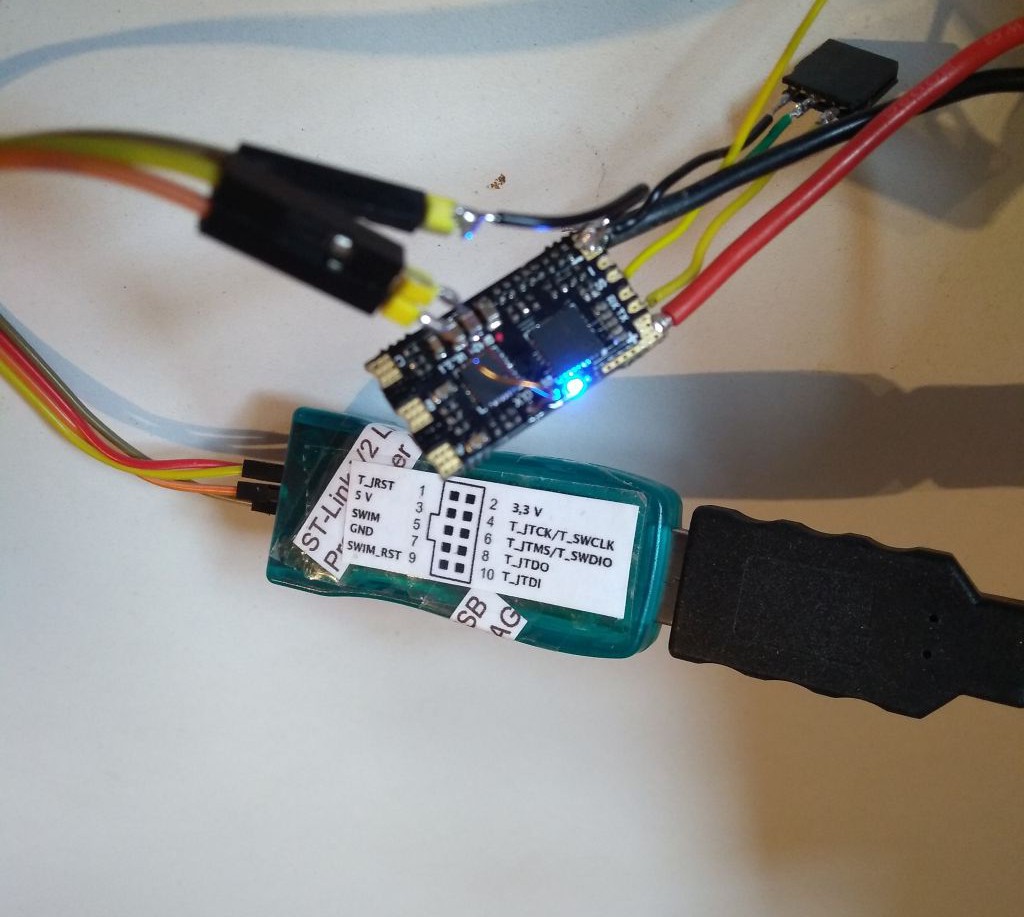
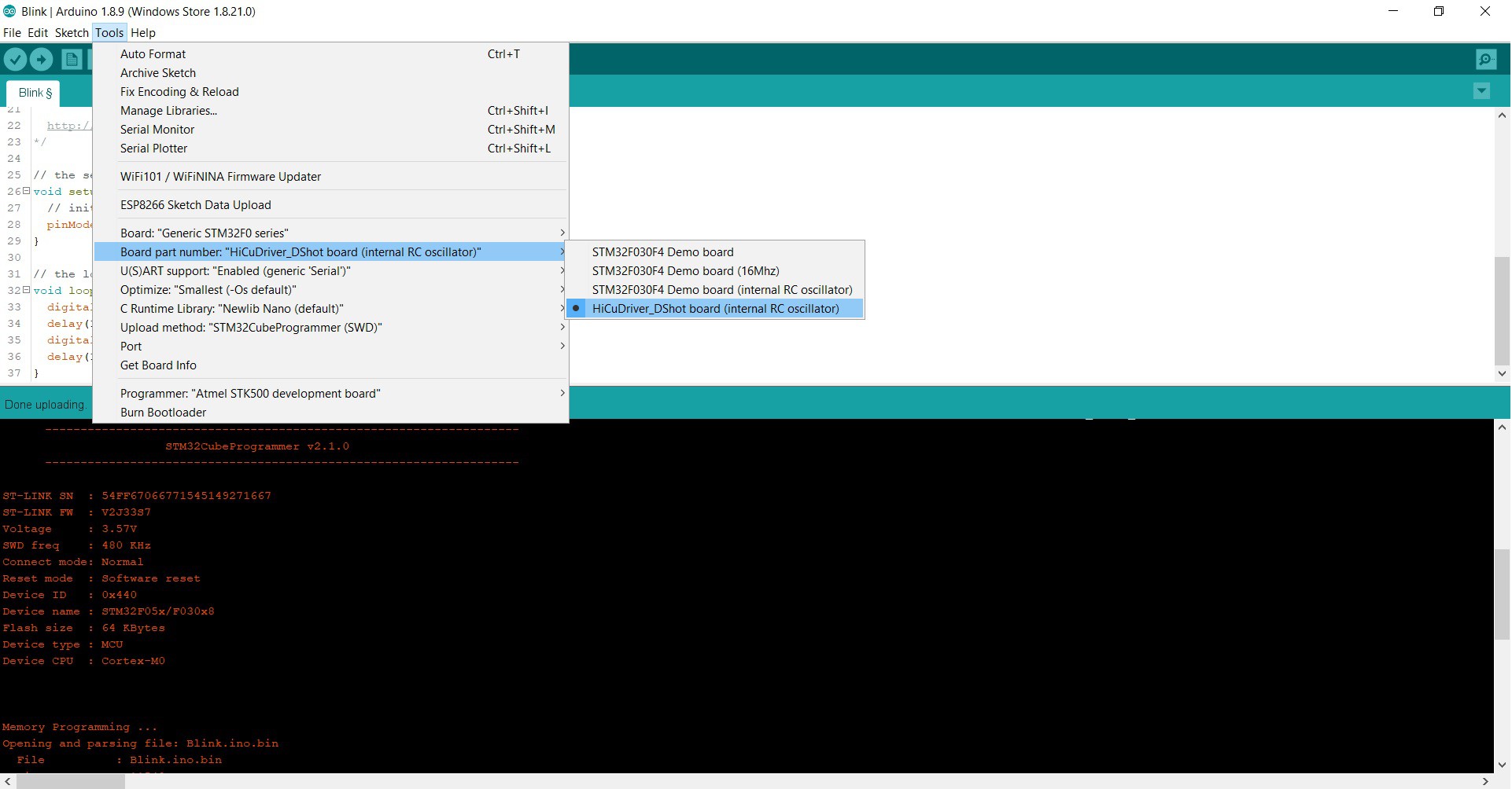 To run a blink sketch the following is to do.
 Lithium ION
 ElectroBoy
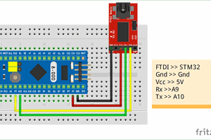
 Electroniclovers123