 EtchedPixels
I ran out of slots. 12 is not enough, and I didn't feel comfortable trying to do 24 or 36 slots with active termination because.. lets face it.. termination is deep magic.
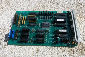
Instead the board is a combination of buffers driving the unidirectional signals onto the secondary bus, some very generic decode logic to match a specific 8bit port, and a very standard bidirectional 8bit I/O port that happens to be wired to the data bus of the secondary.
When the low 8bits of the I/O port in question match, the request ends up on the secondary bus with the upper 8bits of the port remapped to the lower bits on the secondary bus. The data bus is buffered in the right direction according to the R/W lines. The first version has a slight glitch in that I forgot to add jumpers so you can avoid driving RX/TX across the boards when they are in use on the primary (as would be normal). Hence the pin sticking out in the picture.
0.2 should fix that but will not get tested until the next PCB orders.


 Keith
Keith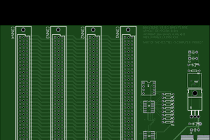
 Samuel A. Falvo II
 SHAOS
SHAOS
Right now
Z80 CPU card
512K/512K RAM/ROM
Z80DMA card
CF adapter
RTC
TMS9918A video
PS2 keyboard/mouse
Clock generator
4 port serial
Dual serial
SAA1099 sound (at the moment, usually an AY-3-8910)
Floppy controller
which isn't enough to then add Z80 PIO, PPIDE for real hard disk, SC129 debug card, and multi-i2c card 8)
I've been taking a break doing other more sociable online things but the reason for the dual port shared memory card work is that once I get back to it I want to put an I/O processor the other end and move the serial ports, some SPI SD cards and networking etc off the main board onto a second CPU (possibly a 68HC11 so the SPI is easy) rather than just the bus extender trick and run it more like the classic bigger systems with the I/O offloaded and maybe even try and push as far as having Fuzix offload the line editing and input modes on the tty/serial ports to the co-processor the way System 5 Unix could.