 Patrick Van Oosterwijck
In the last update I reported that I needed to find a way to reset the W5500 after power-up from PoE for it to initialize correctly. I found some time to work on that yesterday.
Resetting something isn't particularly hard, the main problem I had to deal with was doing it as simply as possible because I have no space for anything fancy on this tiny board. So I started out the simplest way I could think of. Since the W5500 datasheet mentions that there's a 77K nominal pull-up resistor on the RSTn pin, I decided to just add a 0.1uF capacitor from this pin to ground. The simplest reset circuit, the idea being that the RSTn would release with a little delay after power came on.
I scraped the solder mask off a GND connected via and soldered a cap to it on the bottom of the board.
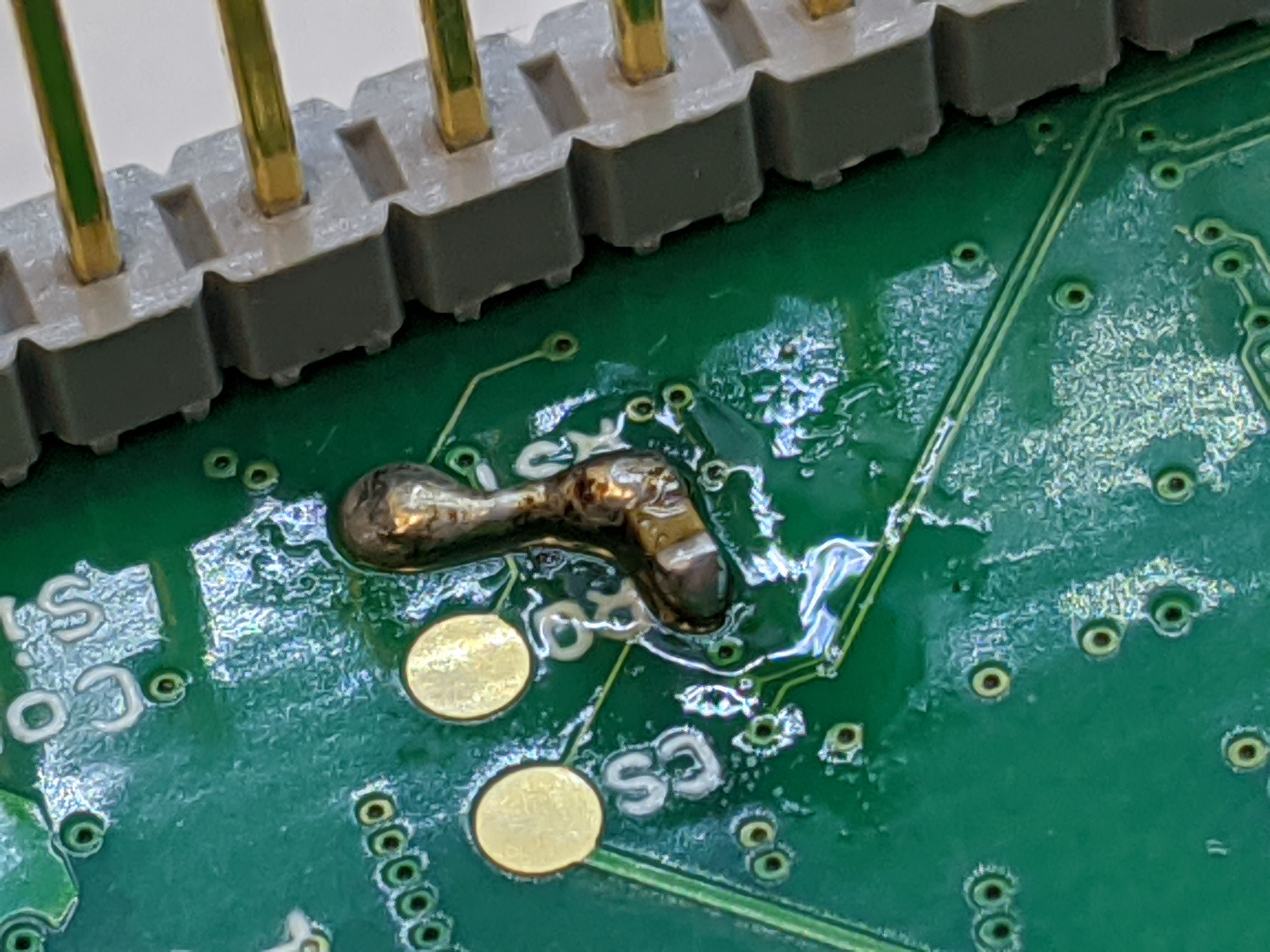
It worked! :) Then it didn't. :(
The first time plugged in, the PHY came up correctly. Then unplugging and replugging, it didn't. What was going on? I decided to measure the voltage on the cap, and found that it was still at 2.5V or so after the power was removed. Discharging very slowly. I decided to short the cap and plug it in, and the PHY came up correctly. My cap was just not discharging when the power went away.
It seems the pull-up "resistor" is actually a highly resistive PFET that isn't active when the chip is off. This is a very common thing to do for pull-ups on chips, since FETs are much smaller than resistors on chips, and size equals cost. But I had expected that the cap would still discharge through the ESD diode that typically goes from a chip IO to the positive power supply. Turns out the W5500 has 5V tolerant IOs, which means the ESD protection has to be implemented differently (likely with zener diodes) and there is no diode going from the IO pin to supply. Hence no discharge path for the cap on RSTn when power goes away, only self-discharge.
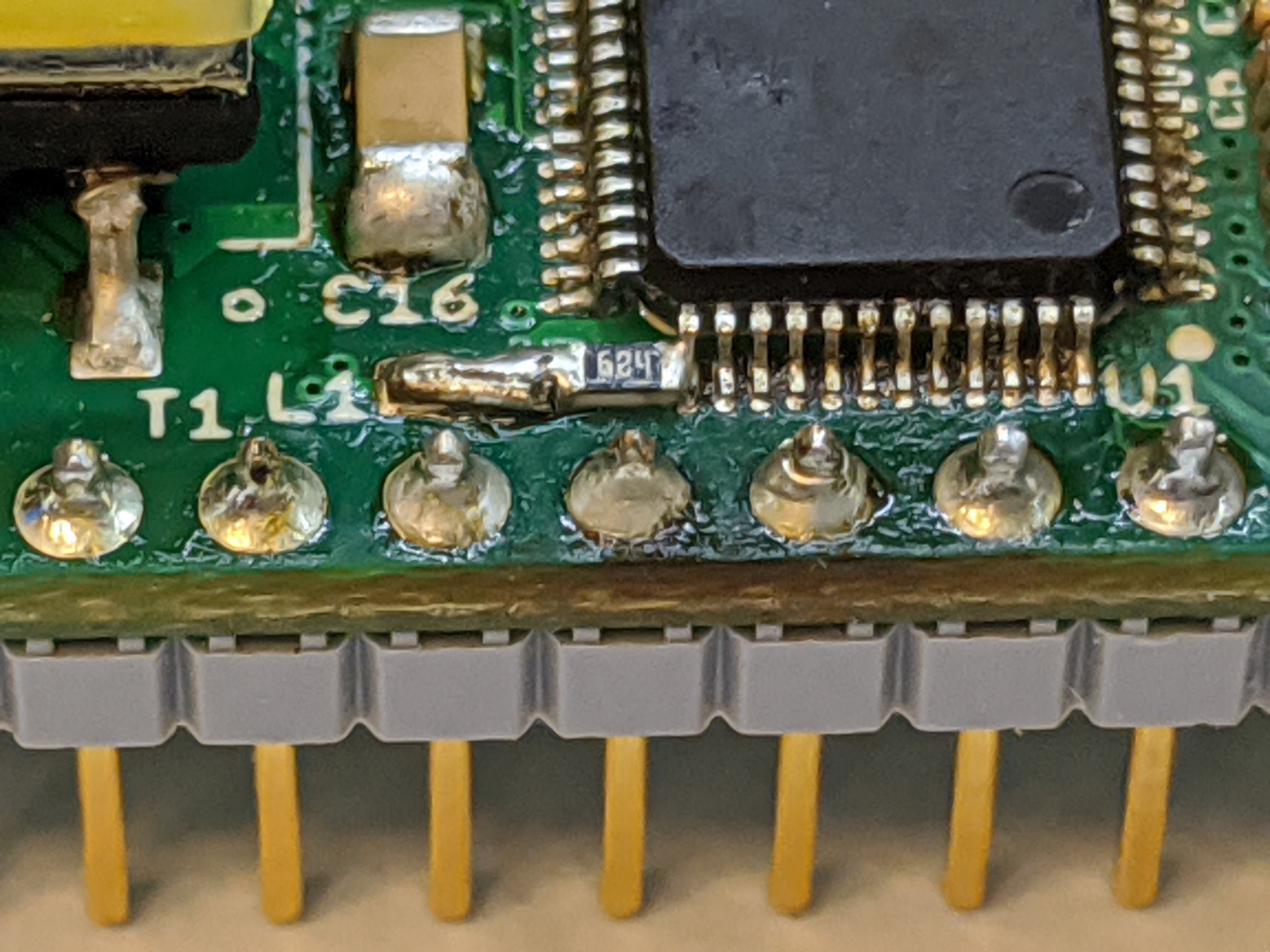
Unfortunately this means adding another part, a diode or resistor. Resistor hopefully, since it's smaller and cheaper. I added a 680K from RSTn to VCC. As I had been considering where I could possibly fit this parts, I decided to get rid of ferrite bead L1, since that seemed like the only good place for these extra parts to go. Filtering the PHY power supply is a good thing, but likely not a make of break situation like the PHY not initializing correctly. Space-wise, I was going to have one or the other and that made an easy choice, but I needed to check it would indeed work without the bead.
Tried it and... success! The W5500 would initialize correctly every time!
I implemented this on both prototypes and it works good. When L1 is gone, I can fit this new capacitor and resistor in 0402 package on the top side of the board where L1 was, keeping it single sided. Time to implement all changes in a rev 2 PCB layout!
Discussions
Become a Hackaday.io Member
Create an account to leave a comment. Already have an account? Log In.