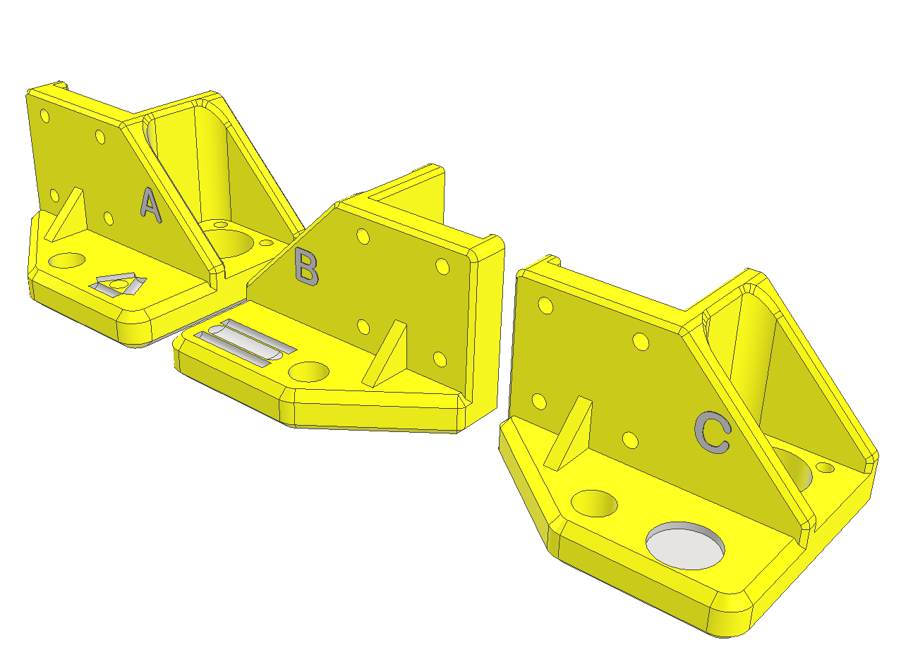
Picking up with the Kinematic Z Yokes, I've created the 3 versions. I labeled them A, B & C.
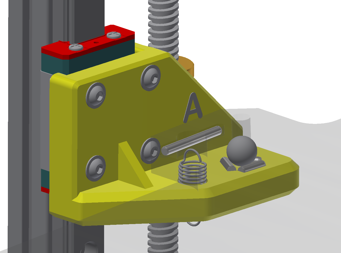
Ball A will pin the bed at the A-corner as the ball rests inside 3 pins
Ball B will be allowed to move linearly in the Y axis as it rests between 3 pins
Ball C will be allowed to translate on X or Y

Above are the 3 Z yokes, all derived from a master version.

The ball would be an 8mm diameter or 5/16 inch. https://www.amazon.com/7-938mm-Silicon-Nitride-Ceramic-Bearing/dp/B07D8VQ2GB/. Ceramic has low thermal conductivity, SiN4 has a thermal conductivity as low as 10 W/m-K. I could go with glass spheres as well.
The pins are all 2.5mm, and either 8mm long or 20mm long.

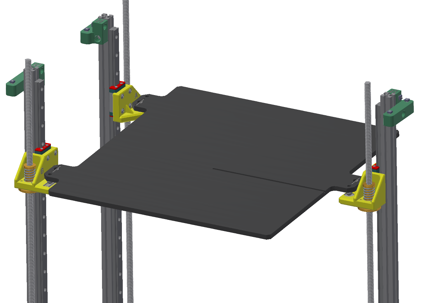
Here is the assembly, it will tolerate a fair amount of angular misalignment without binding, not really planning on allowing a worst case situation.
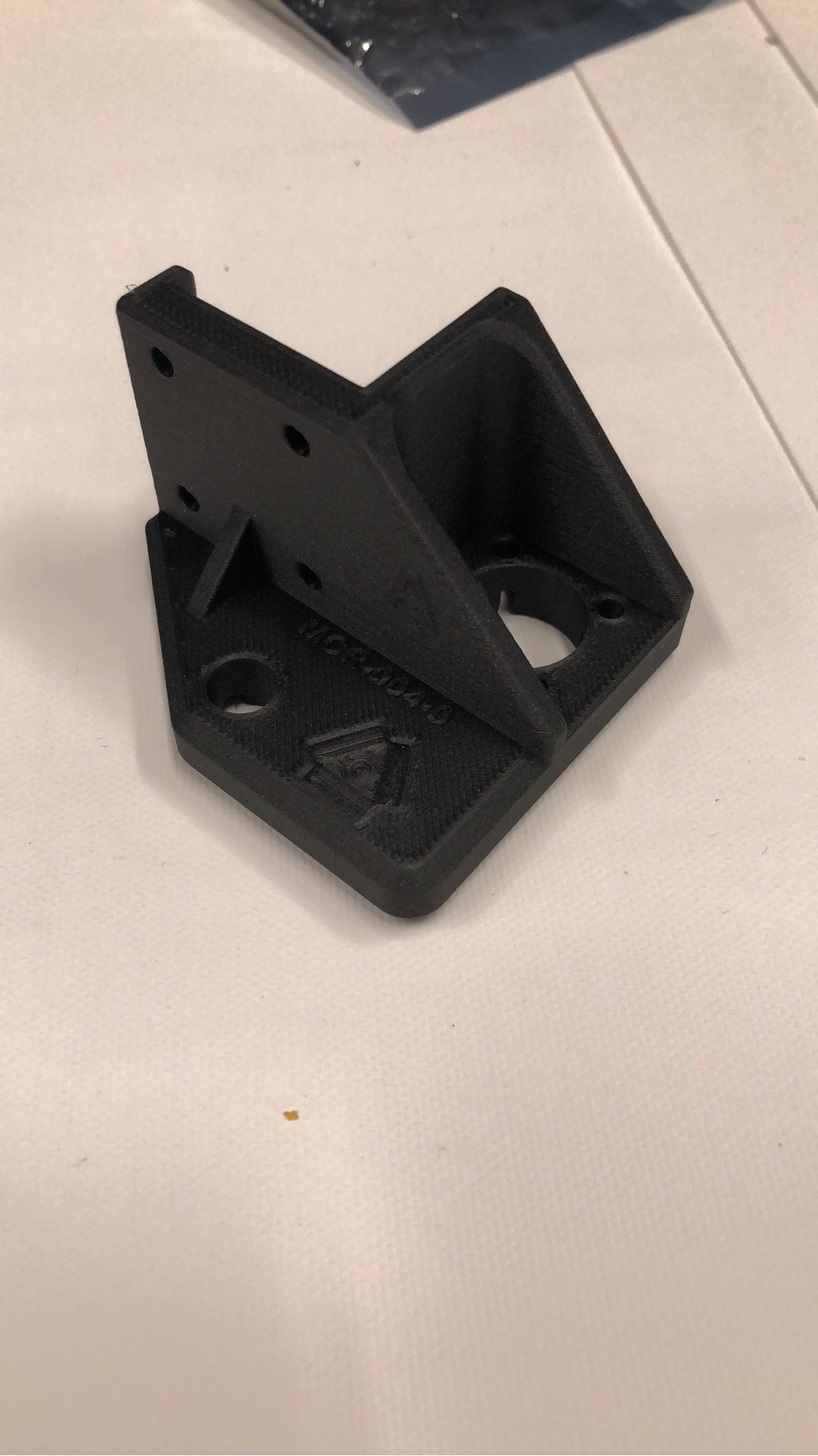
Z axis kinematic mount printed in Onyx w/Carbon

 Patrick
Discussions
Become a Hackaday.io Member
Create an account to leave a comment. Already have an account? Log In.
how’s this working out for you? Would you be willing to post the STL files in the gh repo?
Are you sure? yes | no