 George Gardner
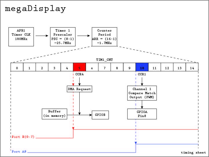
Please study the goodness that is the above image. The display driver I wrote is free-running, constantly outputting the contents of a buffer in memory to the GPIOB port via DMA while taking care of the clock pulses using the same timer via PWM. The trick here is to sent the DMA request prior to the CCR1 compare match (and therefore clock signal high).
The red & blue lines represent the signal on the GPIO pins as if they were viewed on an oscilliscope. As you can see, at an approximate 1.7Mbps, we'll be able to achieve a solid framerate. Besides, we'll need those extra frames if we want any sort of bit depth.
So we've setup timer1 with a 15 count period, setup TIM1 Channel 4 to request a DMA transfer at compare match with CCR4, setup TIM1 Channel 1 to output a PWM, using CCR1 as a compare match. Note the PWM is in 'LOW' mode, meaning it stays low until it experiences a compare/match with CCR1, then goes high.
"But how do we handle row switching,?" you may ask. This is where ISRs come into play. We basically count the number of overflow events (timer CNT reaches ARR, then resets back to zero), so we know how many pixels we've shifted out. Once we have shifted the last pixel in the row, we stop the timer, toggle the latch and OE pin, set the pins to the appropriate row on the GPIO port, then again toggle the latch and OE pin to latch the data and enable the output. We then start the timer to repeat the sequence.
But wait, it's not that easy. ISRs take time. With a clock running THIS fast, by the time we enter an ISR routine in software and disable the timer, we may get ~1-4 extra clock pulses for each row. This clearly won't work in its current state.
The solution is to use two different Timer tools at our disposal. The first is the repetition counter (RCR) and the second is one pulse mode (OPM).
The repetition counter is a register that will count down at every overflow event on the timer it is setup for. When the repetition counter reaches 0, and only when it is at 0, is when an overflow will trigger an ISR AND an update event will be generated. It is important to note that an update event will not be generated on timer overflow until the timer overflows WHILE the RCR is at 0x0.
With this, we set the repetition counter to 255. Remember you need an overflow while RCR is 0, so zero is counted, and 256 pulses will output before the ISR is triggered and the update generation event occurs. The update generation event is automatic, and reloads the contents of the ARR, CCRx, RCR, etc into the shadow registers -- this is because they are double buffered in this mode.
So this allows our ISR in software to not be triggered until an entire row has been shifted out. This is great, as it's one less thing we have to keep track of in code, and it is automatic. But how do we stop the clock to prevent extra pulses from getting in? Remember the timer is still counting when we enter the ISR, and if you're not fast enough (and you likely won't be at this speed) then your data will start spewing into rows it should not be.
Enter the OPM. One pulse mode stops the timer at the next update event. This is great in that now our timer is stopped via hardware immediately after the row has shifted out (remember we're not generating update events until RCR=0, and therefore not until the entire row has been completed). This leaves our ISR in software to only have to worry about toggling the OE & LAT pins, selecting the next row via the LED Display's A & B pins, re-toggling the OE & LAT pins, then restarting the timer.
Discussions
Become a Hackaday.io Member
Create an account to leave a comment. Already have an account? Log In.