 Rory
RoryMy test setup consists of the following parts which were all built for this project:
Battery pack:
The battery pack consists of 4 Samsung INR18650-25R cells mounted in a wooden frame. The cells are spaced 3.5mm apart to allow cooling pipework to be installed. The cells are connected in series via spot welded nickel plated steel strips. Three 10KNTC thermistors measure the following:
- Cell at edge of pack
- Cell at centre of pack
- Centre nickel strip
The power connection to the battery pack is via 14AWG silicone cables to an XT60 connector to allow disconnection in an emergency.
During testing the battery pack was insulated from its surroundings to simulate being in the centre of a larger battery pack (all local cells would be at the same temperature so no movement of energy)
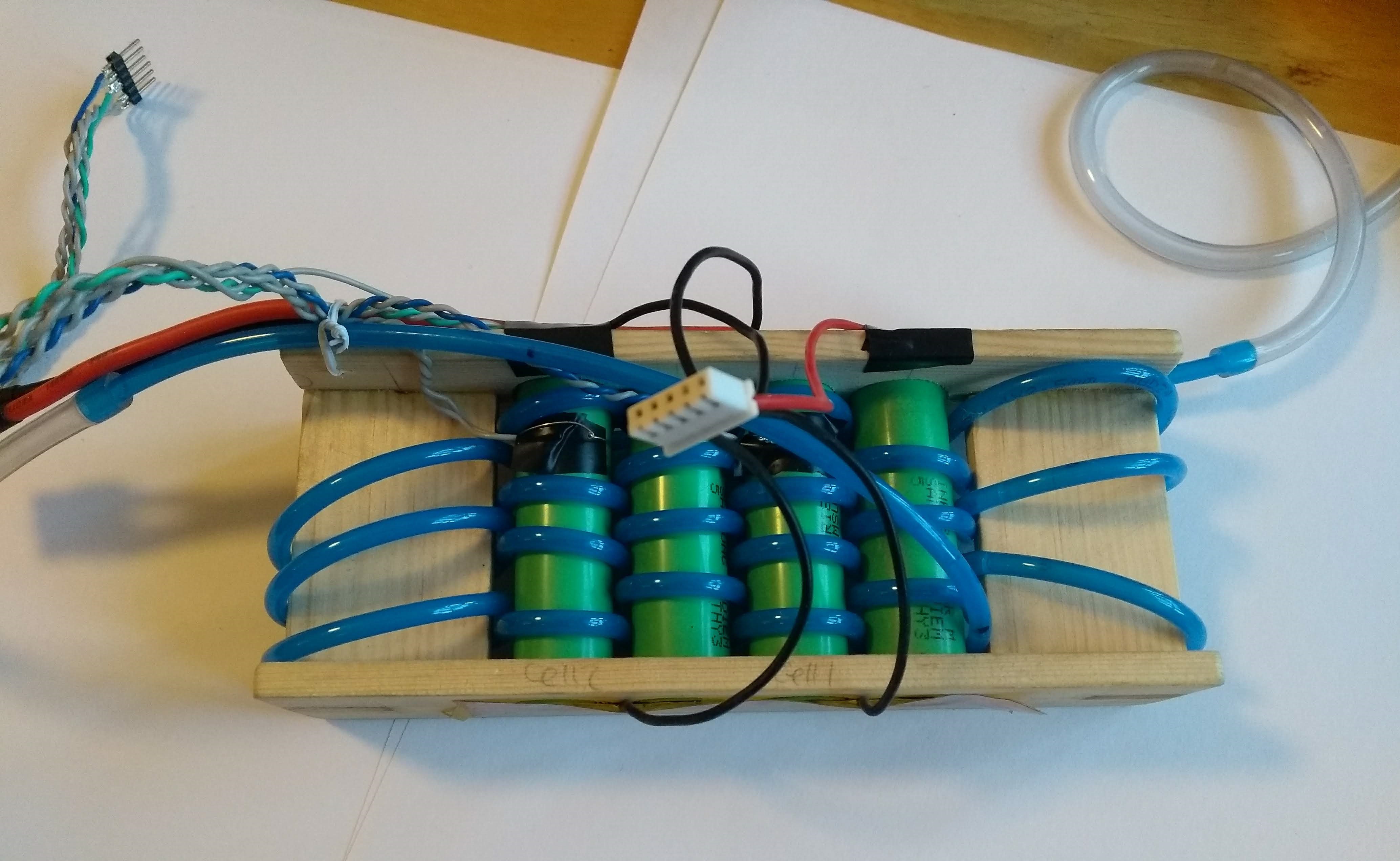 |
| Above: Battery pack with cooling tubing and temperature sensors |
Water cooled dummy load:
This horrible looking device is a high-power Mitsubishi QM300HA-2H triple FET (salvaged from a vintage motor drive) fixed to a water cooling block along with a .05ohm current sense resistor. An op amp and MOSFET provide the not insignificant current required to drive the triple. A potentiometer provides current adjustment. The water-cooling block is fitted with a shower hose to allow the device to be easily coupled to the shower in my bathroom. The device would be set to discharge the battery at 20A which is the maximum continuous rated discharge of the cells. The dummy load did occasionally oscillate causing the current to be uncontrolled. This requires further investigation. Discharge current was monitored with a clamp meter throughout the testing.
Please note this was a quick and dirty way to get the job done. Not my finest work!
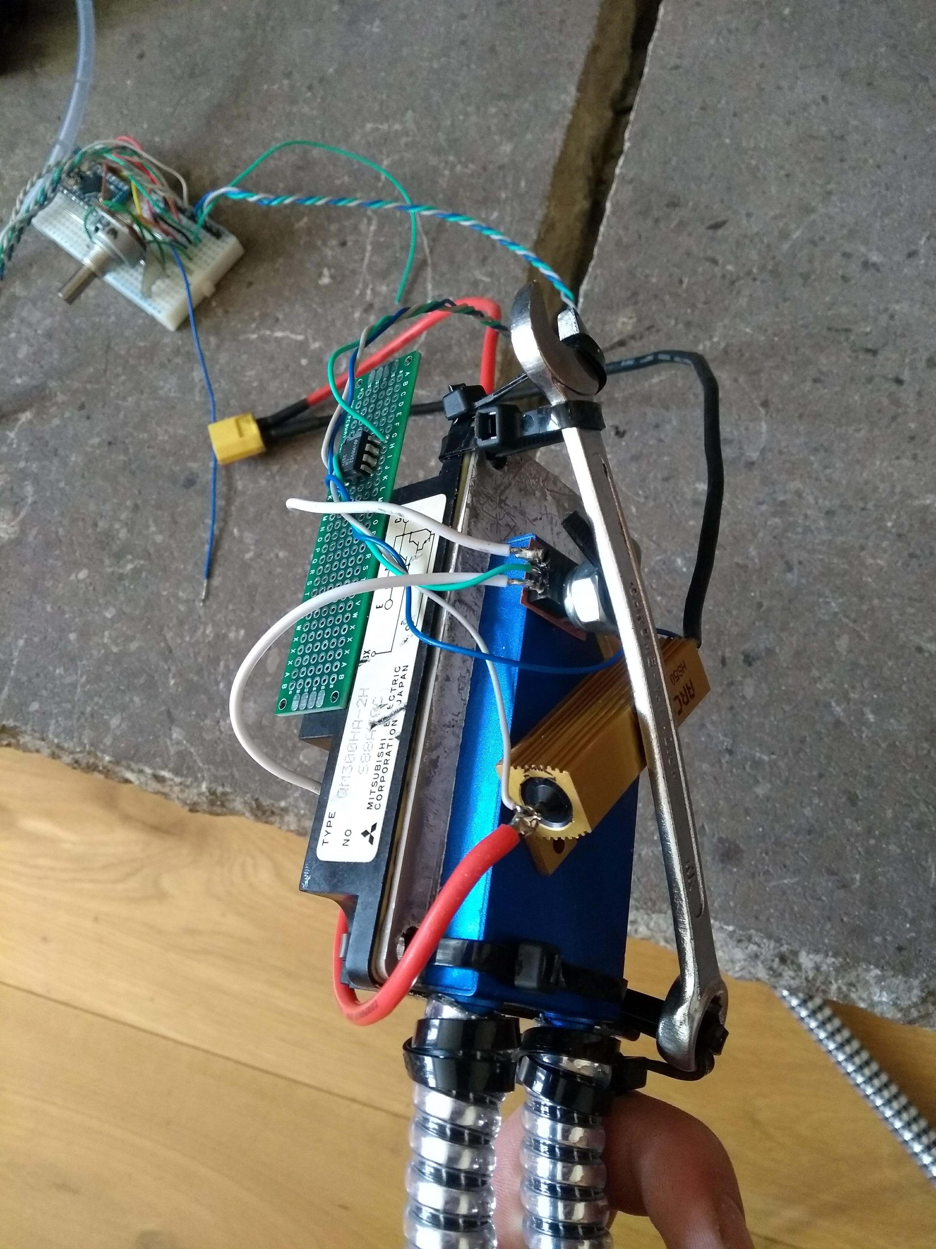 |
| Above: Water cooled dummy load. Spanner provides clamping tension |
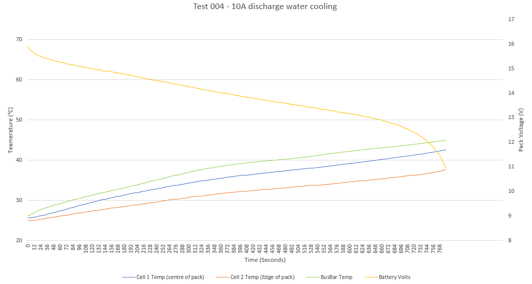
Arduino Data Logger
An Arduino controls the test period and monitors the battery voltage and temperature. The Arduino communicates with a laptop via the USB serial port. Putty is used to send commands to the Arduino to start the test. Once the test has begun data is streamed to the laptop which can be logged to a file and later imported to excel. The Arduino will stop the test if any of the temperatures exceed pre-set limits or the battery voltage falls to low.
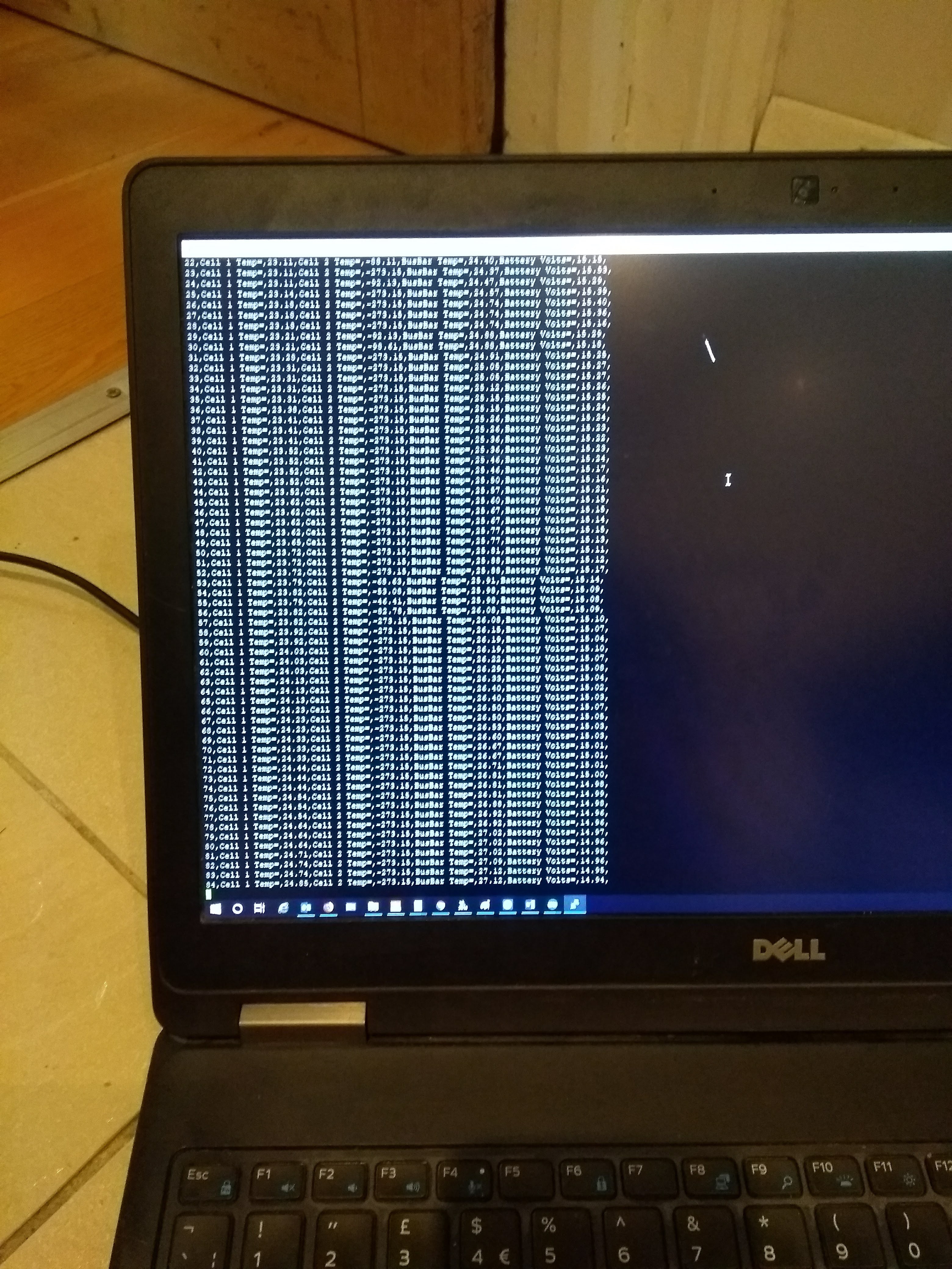 |
| Above: Serial data during test |
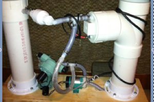
Water cooling system
The water-cooling system consists of a car windscreen washer pump. It is a generic item from ebay, not a specific manufacturer as far as I can tell. It is a gear pump intended to run on 12V. It quickly became apparent that the pump is not rated for continuous operation at 12V. The motor gets very hot. All tests were carried out with the pump running at 6V. Even at 6V the motor gets to alarming temperatures. I would suggest using a better pump for similar experiments.
A measured quantity of water is stored in a glass jug which is pumped through the battery. The temperature is monitored via a brewing thermometer. The jug was not insulated so can gain energy from its surroundings as well as the energy removed from the battery.
Flow rate is approximately 330ml/minute
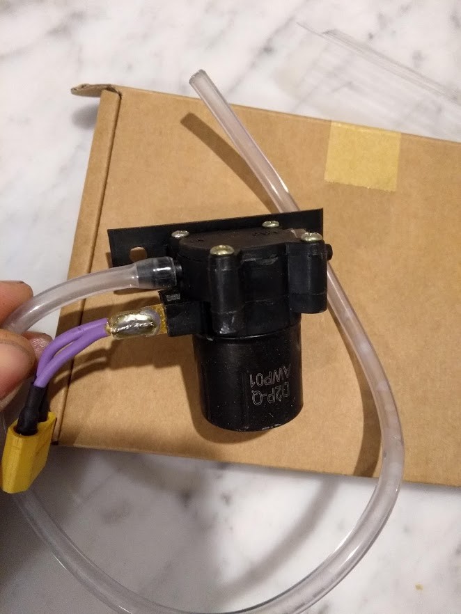 |
| Above: Ebay pump. Do not use. |
Thermal interface to cells – 4mm pneumatic hose
The cells were placed in the mounting frame to allow 4mm pneumatic hose to be threaded between them. Each cell is covered by 7 180° wraps of tube (later increased to 12). Coupling is poor due to the round outside diameter of the tube. All testing to date has used this method
 |
| Above: Pneumatic tube threaded around cells |
Thermal interface to cells – 25mm lay flat hose
25mm lay flat hose was chosen because it could be threaded between the cells providing a much larger surface area of contact. The ends of the hose were coupled to the pump via barbed fittings soldered to copper plumbing end caps.
Thermal testing with this method was not attempted. The walls of the lay flat hose are very thick and the hose crumples as it is passed around the outside diameter...
Read more »
 ken.do
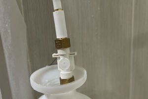
 Scott
Scott