 bobgreenwade
This is a project to make a FeatherWing that allows the Feather to control an internal AM/FM radio -- something that, so far as I've been able to determine, is currently unavailable elsewhere.
The chip used is Silicon Labs' Si4734-D60-GU. This chip is controlled by I2C, which means that a fair bit of coding will be required to make it work with Feather (or any other Arduino or similar system).
The AM and FM antennas are external, as are the amplifier and speakers. The intent is for the board's output to be channeled to an amplifier, though the user may want to somehow process the audio in some other way either before or in place of the amp. To better facilitate this option, jumper holes are provided so the output can be diverted to any two of the Feather's Analog pins.
As a bonus, a Qwiic connector is also included for further I2C expansion. (You can never have too many Qwiic connectors.)
Caveats:
The plans, as they appear as of this writing, are based on educated guesswork. This is essentially drawn from the datasheet for the Si4734-D60-GU, and has had no real-world testing.
 davedarko
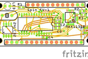
 Kevin Santo Cappuccio
 Ryan Logsdon