Rory
RoryDesign Criteria
- 4 Stereo Inputs
- Must be able to control at least 4 zones (2 bedrooms, lounge and kitchen)
- Outputs will feed class D amplifier modules and control volume and mute function
- All zones will be Bi-amped. High and low pass filters will be provided
- Controllable via I2C
- Individual boards to be 2 layer and <100mm x 100mm in size to take advantage of low cost board houses.
Introduction
I brought a house and it has more than one room. I thought it would be nice to have a central HI-FI system that could serve at least 2 bedrooms, the kitchen and the lounge. I had discovered some very cheep class D amplifier modules on ebay. There are many different options to choose from with varying claimed power outputs. I brought one to test.
My amplifier was marketed as 'TDA7498 2*100W Dual Channel Power Class D Audio Digital Amplifier Board ModuleNM' with a claimed output power of 2 x 100W! A bargain at £9 delivered.
The amplifier was lightly tested and the results were good. The circuit and PCB layout closely resemble ST's test circuit from the TDA7498 datasheet which is reassuring. I expect most of these amplifier modules will be the same.
The datasheet confirms that 2 x 100W is possible but at a THD of 10%. You probably wouldn't want to run it at any more that 50W per channel (THD < 0.1%).
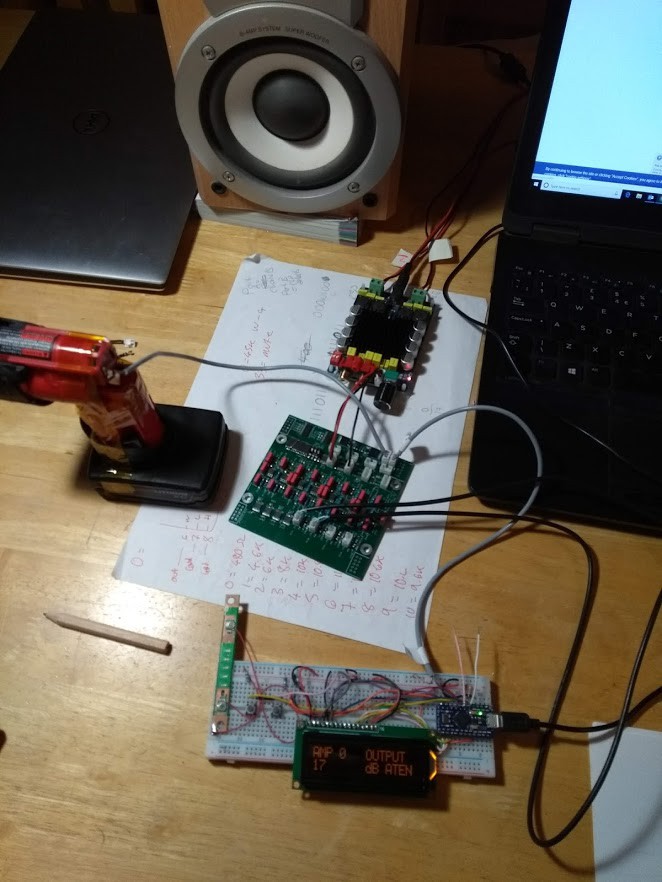
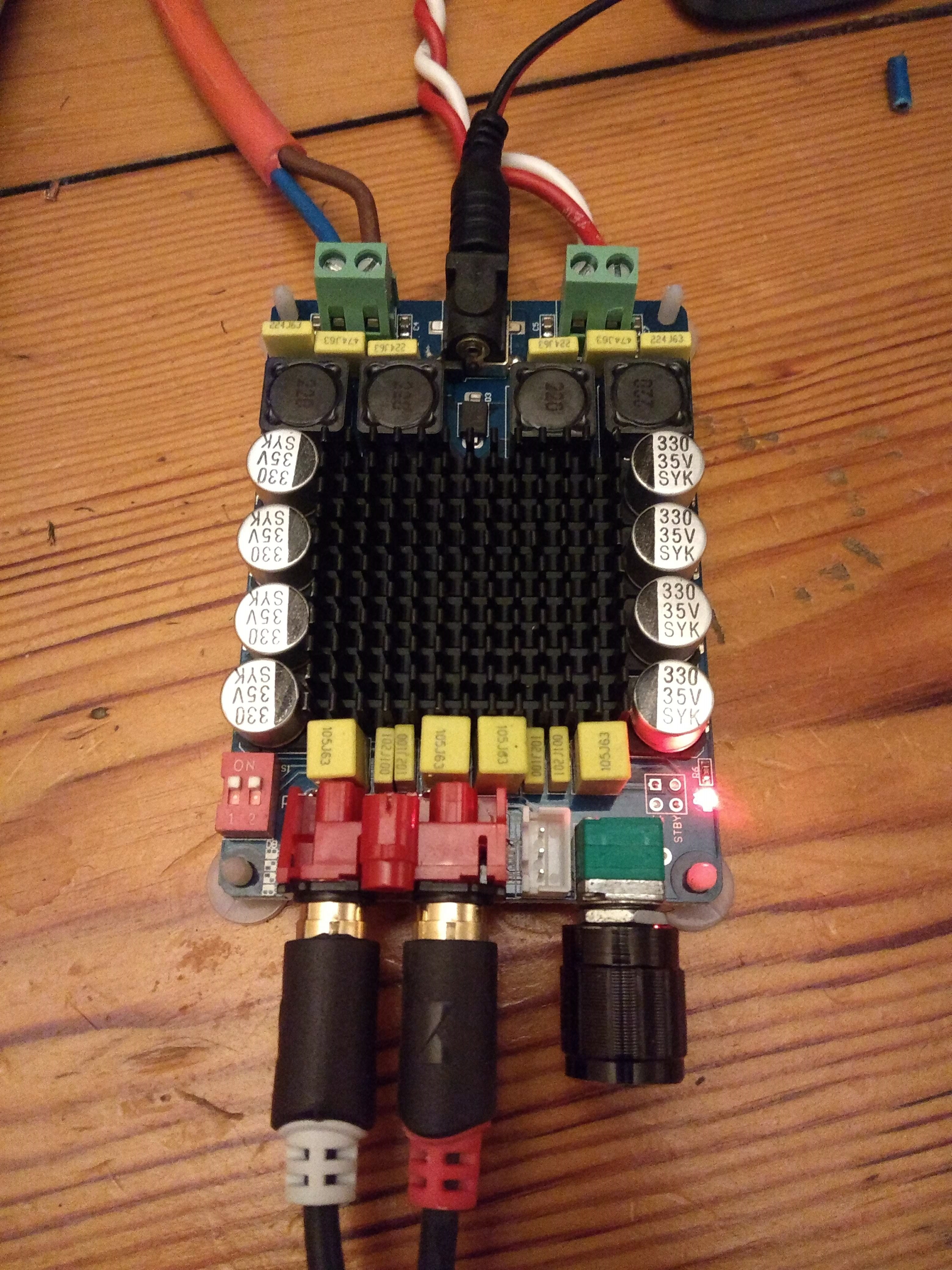 |
| Above: TDA7498 Amplifier |
I decided to build a I2C controlled pre amp that could switch 4 stereo inputs to at least 4 zones.
Each zone would be Bi-Amped (separate amplifier for high and low frequencies) I have had good results bi-amping low quality speakers. I am not an audiophile but when stereo amps are £9 its a no brainier.
PCB Design
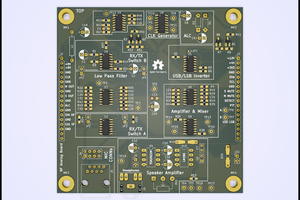
The PCB is designed to daisy chain onto additional boards using right angle pin headers. This would allow each PCB to be kept small to take advantage of low cost PCB prototyping services. All components are on one side for easy soldering using a hot plate.
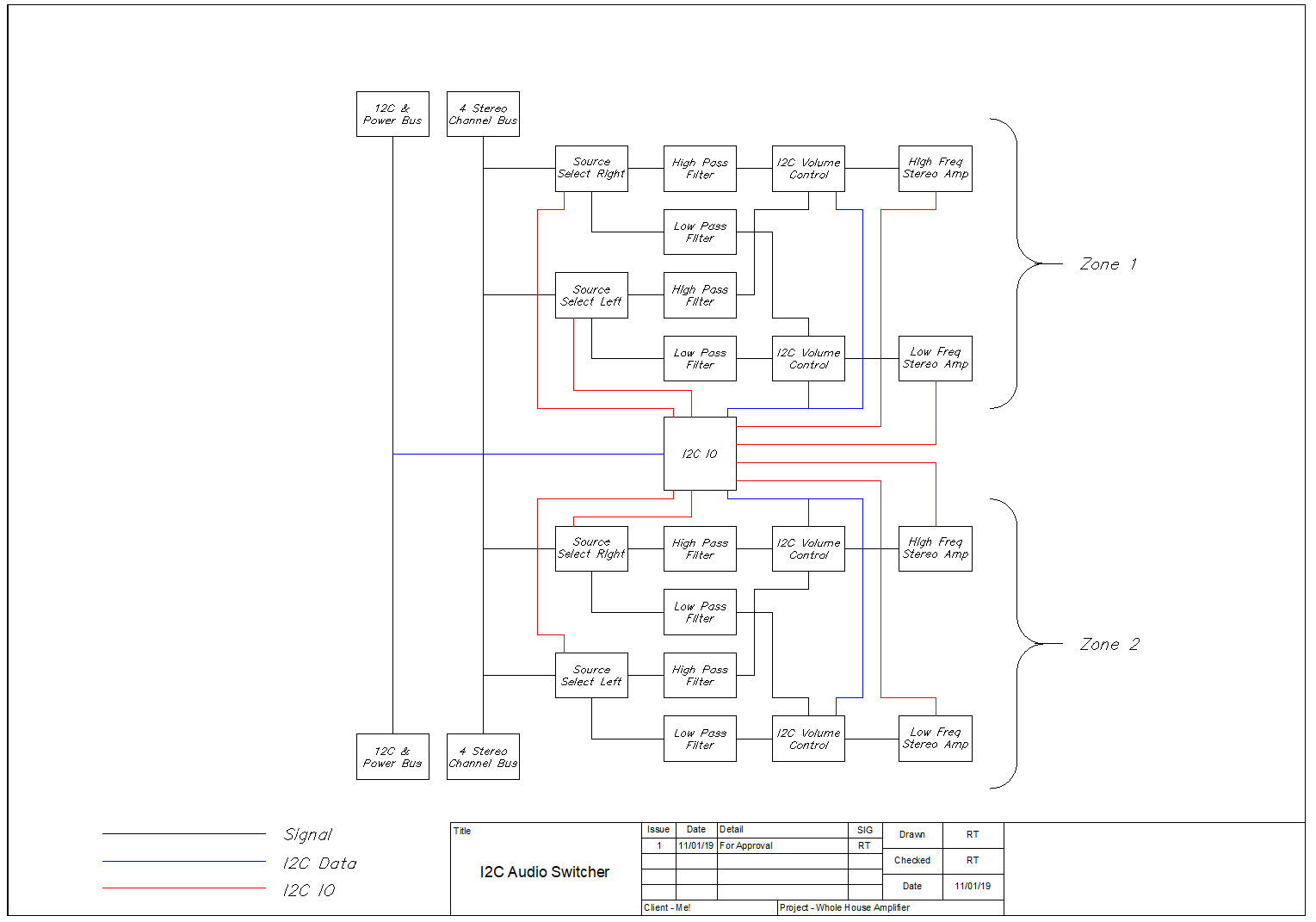 |
| Above: System topology for one PCB |
Audio Input & Selection
Audio inputs are fed through a low pass filter to reject any frequencies above 50Khz. Inputs to each zone are selected by DG413LEDQ 4 channel analogue switches. These are used because they can operate from a dual supply. The analogue switches are controlled by a MCP23017 16 bit I2c IO expander. The IO expander also controles the mute function of the amplifier modules via an optocoupler. The IO expander is addressed via a 3 bit dip switch. This limits the total zone capacity of the system to 16 zones per I2c bus (8 PCBs).
High & Low Pass Filters
I have used Rod Elliott's 18dB/Octave Electronic Crossover as shown here https://sound-au.com/project123.htm providing a crossover frequency of 2.34kHz. The resistors and capacitors that form the crossover are kept as through hole parts to allow easy replacement if adjustment of the crossover frequency is required.
Volume Control
Volume control is provided by DS1882E dual channel I2c digital pots. All pots are on the same I2C address. The CE input is toggled by the I2C IO expander when communication is required to a specific pot. An un-documented feature of these pots is that they take 20ms to become ready to receive data from the I2C bus. Volume of the high and low frequencies is adjusted independently meaning basic tone control can be performed.
Other
Each board has linear regulators to drop the +/- 12V power bus to +/-5V.
JST connectors are provided for the audio inputs, power, I2C, audio outputs and mute. It is intended that the first board on the bus would have all connectors. On additional boards only the audio and mute output connectors would be fitted. Other signals would enter via the power and signal busses on right angle pin headers.
Design Issues With Rev 0 PCB
- Dip switches were too close to MCP23017 and dip switches don't fit on their pads correctly. Operated OK for testing.
- DG413LEDQ pin 12 was not connected to the +5V...
 Jan B.
 Sagar 001