 Timo Birnschein
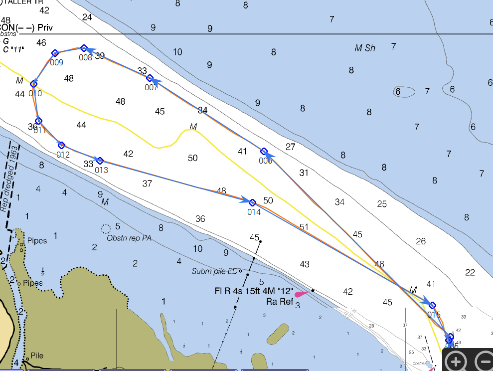
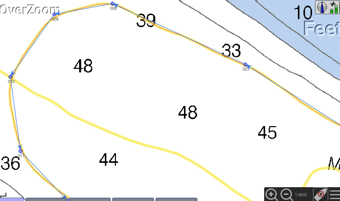
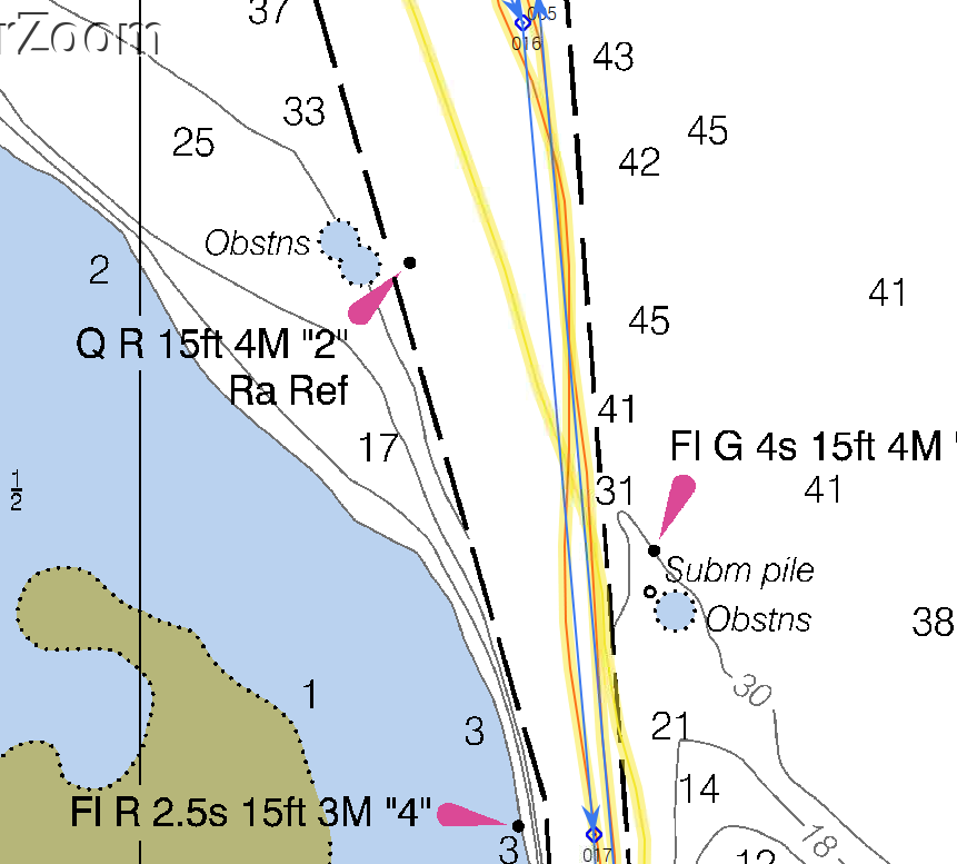
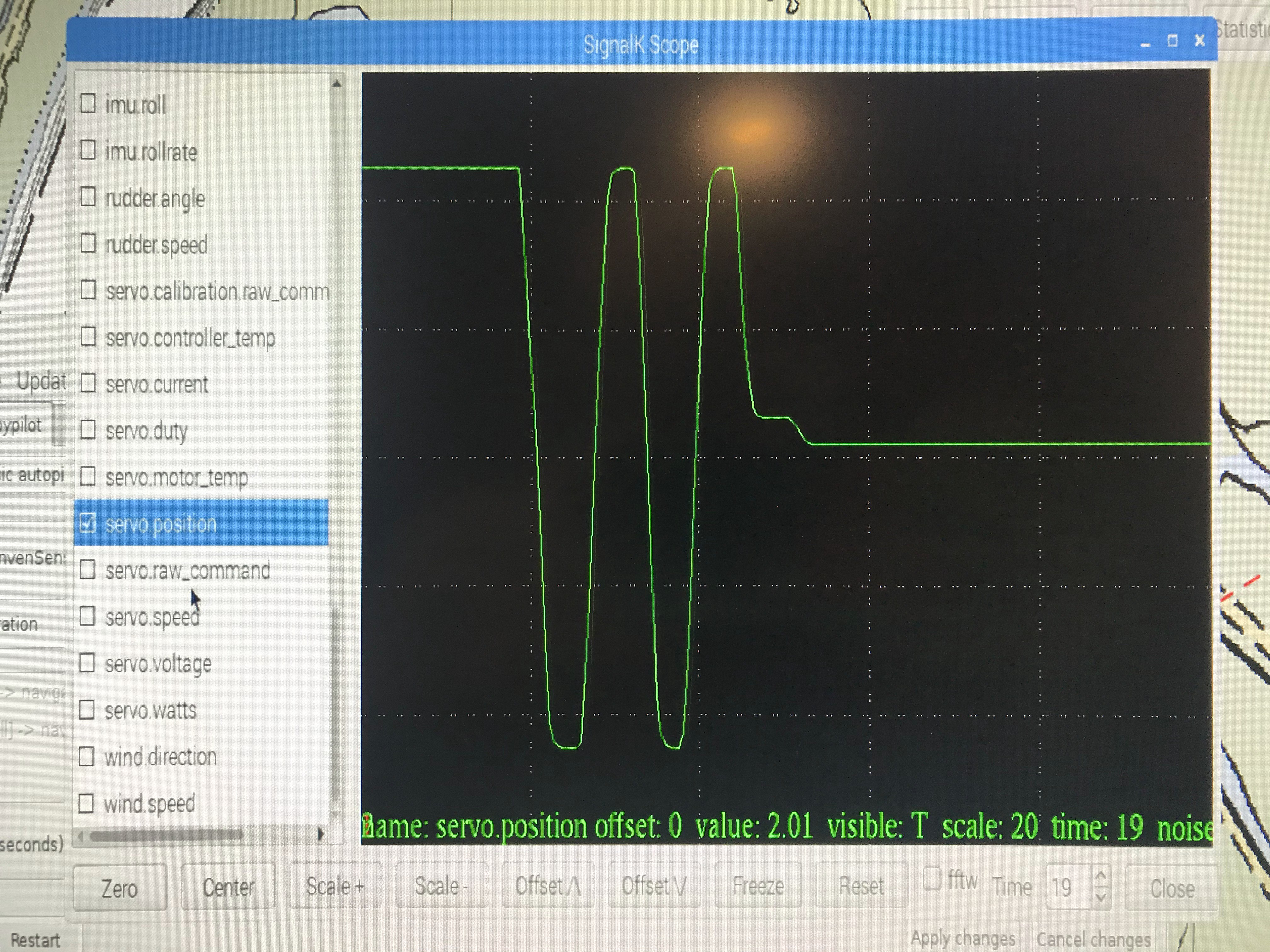
Fast forward a couple very long log entries: It works!
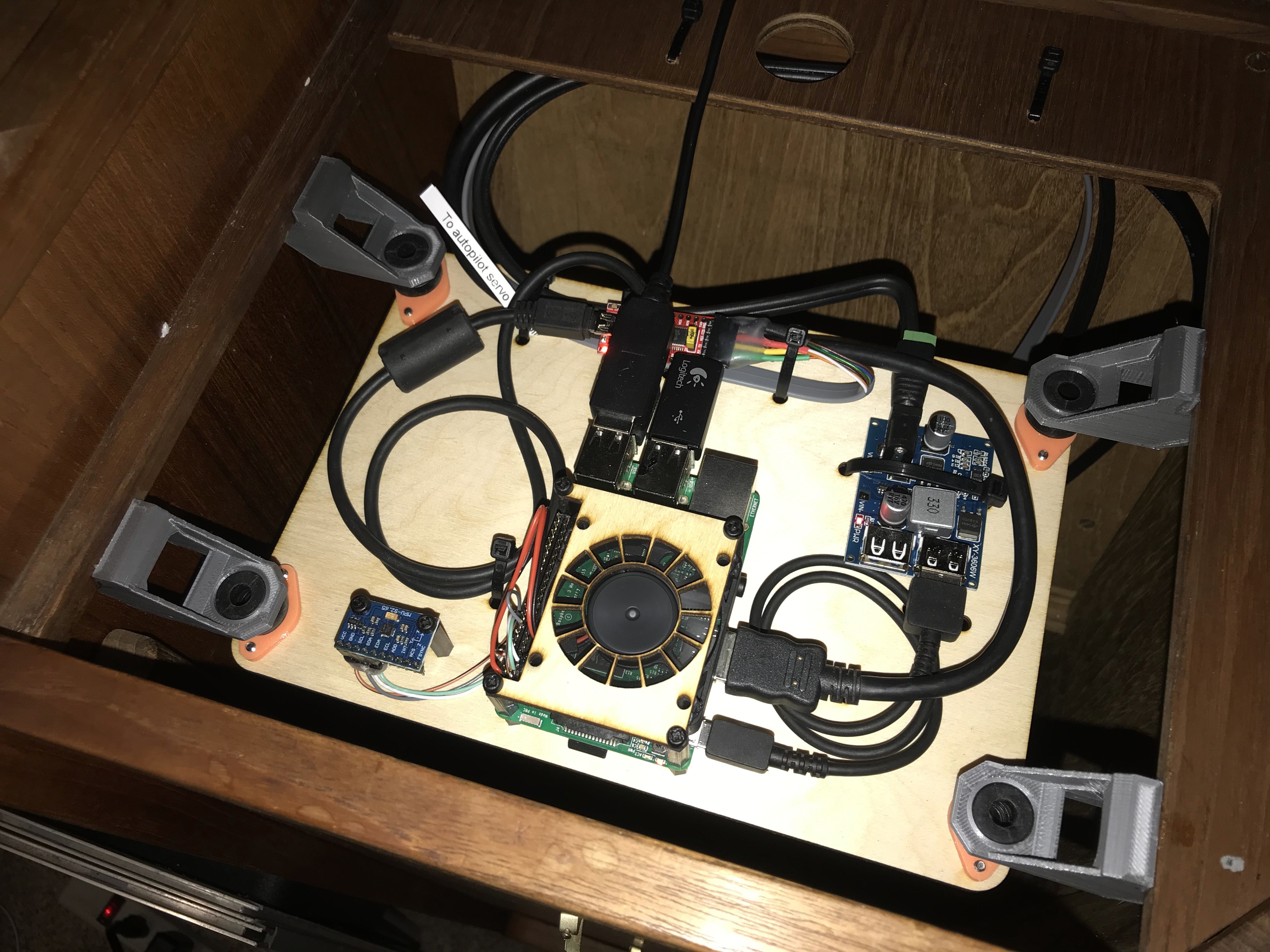
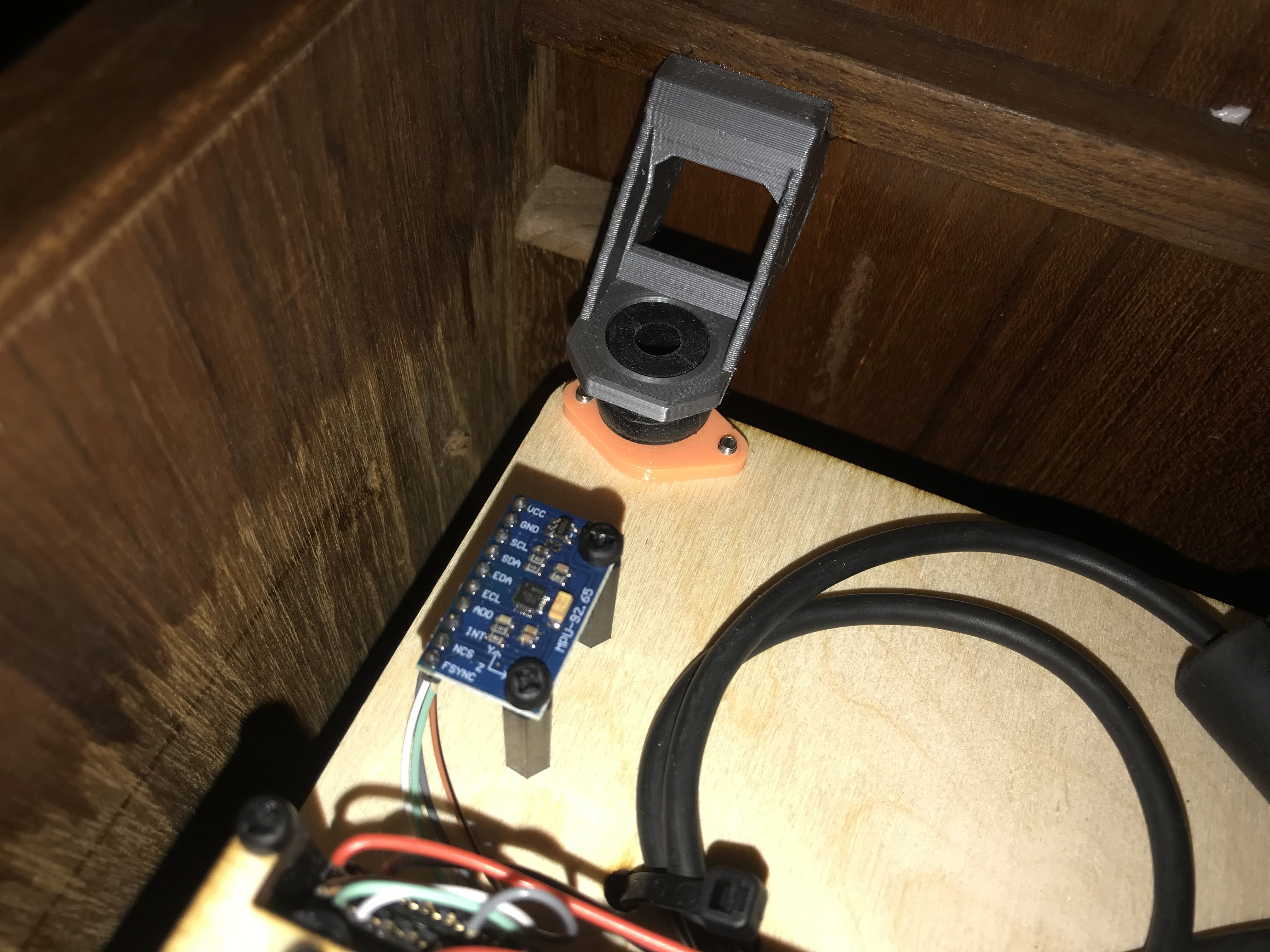
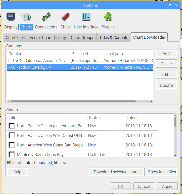
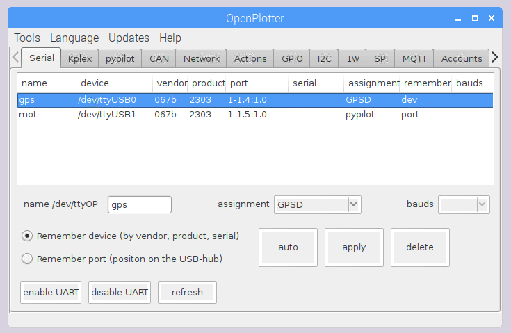
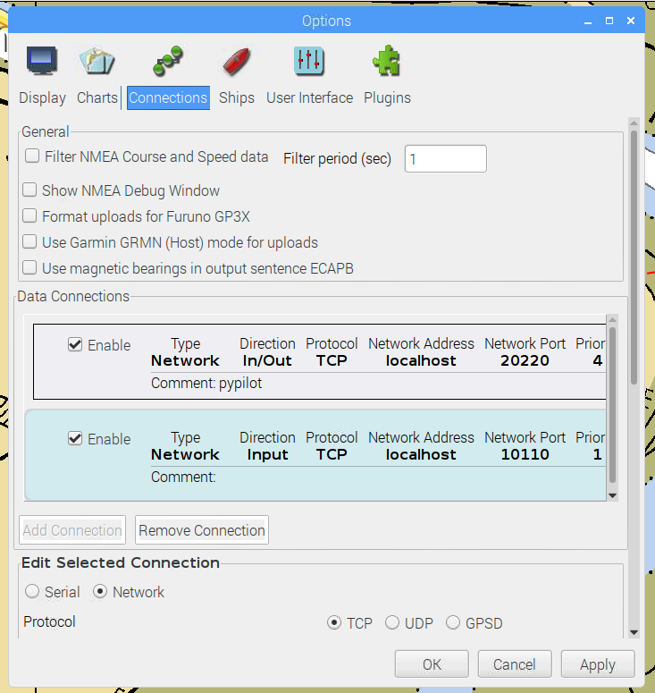
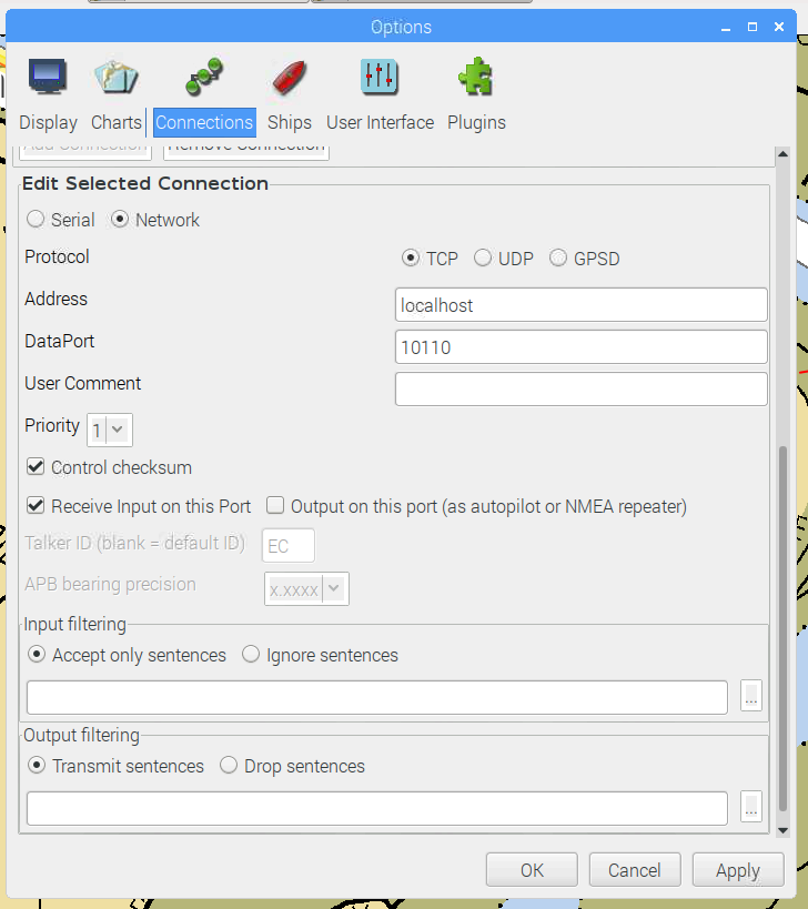
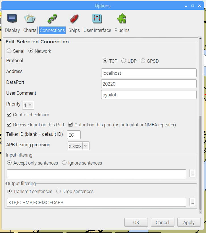
Setting up OpenPlotter using a Raspberry Pi 3B could not be much easier. Just download the ready made image with all necessary software already preinstalled and configured and connect PyPilot to localhost.
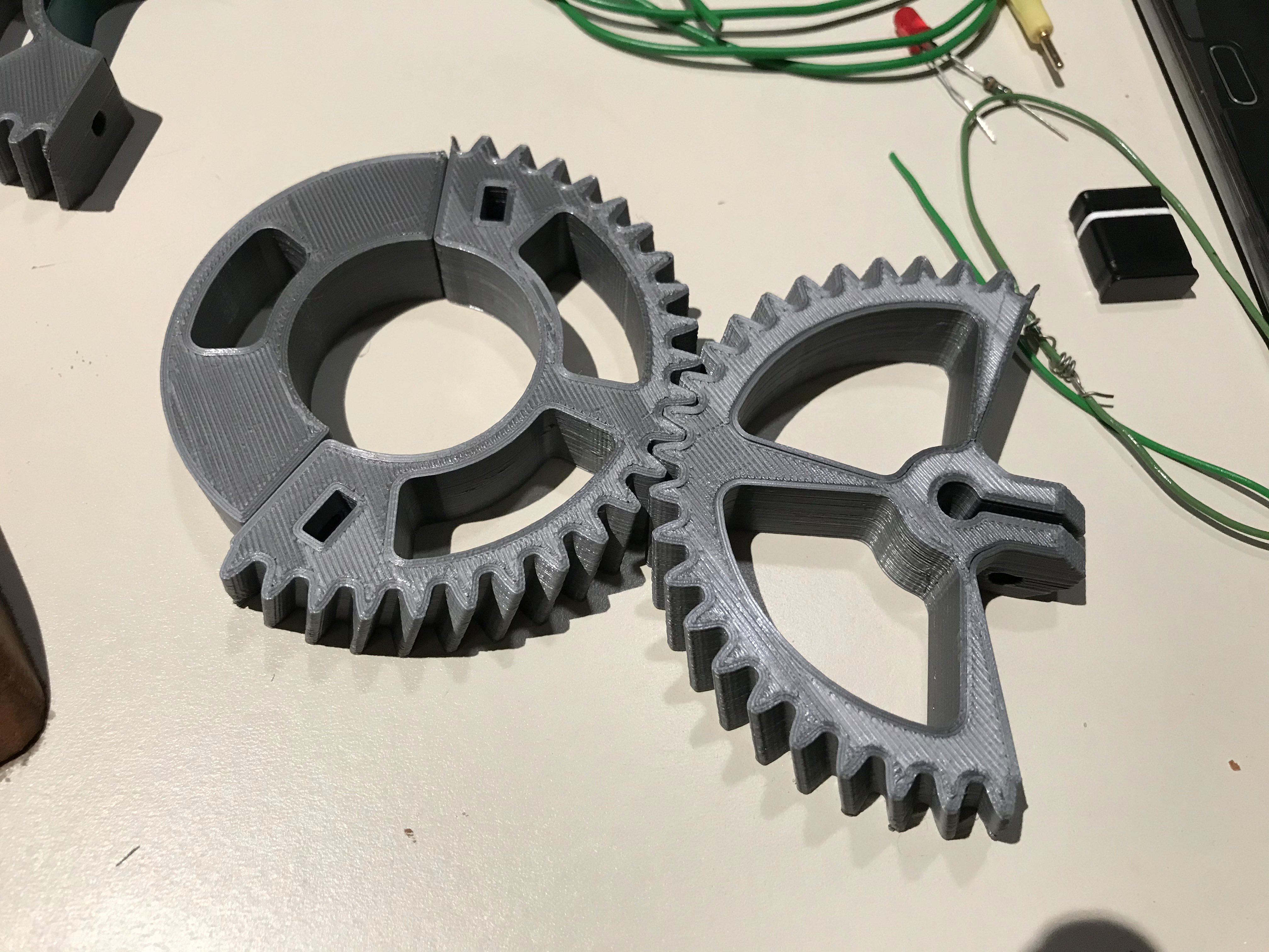
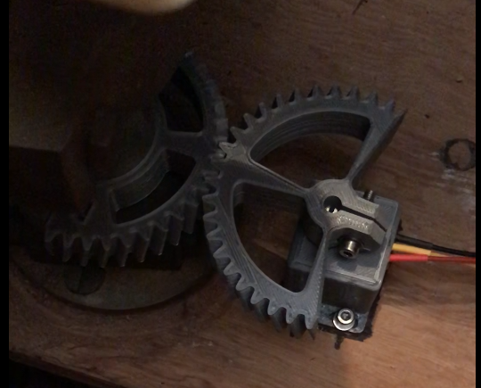
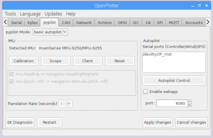
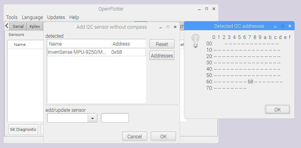
That's it. At least, that should have been it if the pypilot documentation would have been completed already. Unfortunately for me, I needed to read the pypilot motor Arduino code and understand AND rewrite it to be able to put all the necessary hardware together to make the "basic autopilot" work.
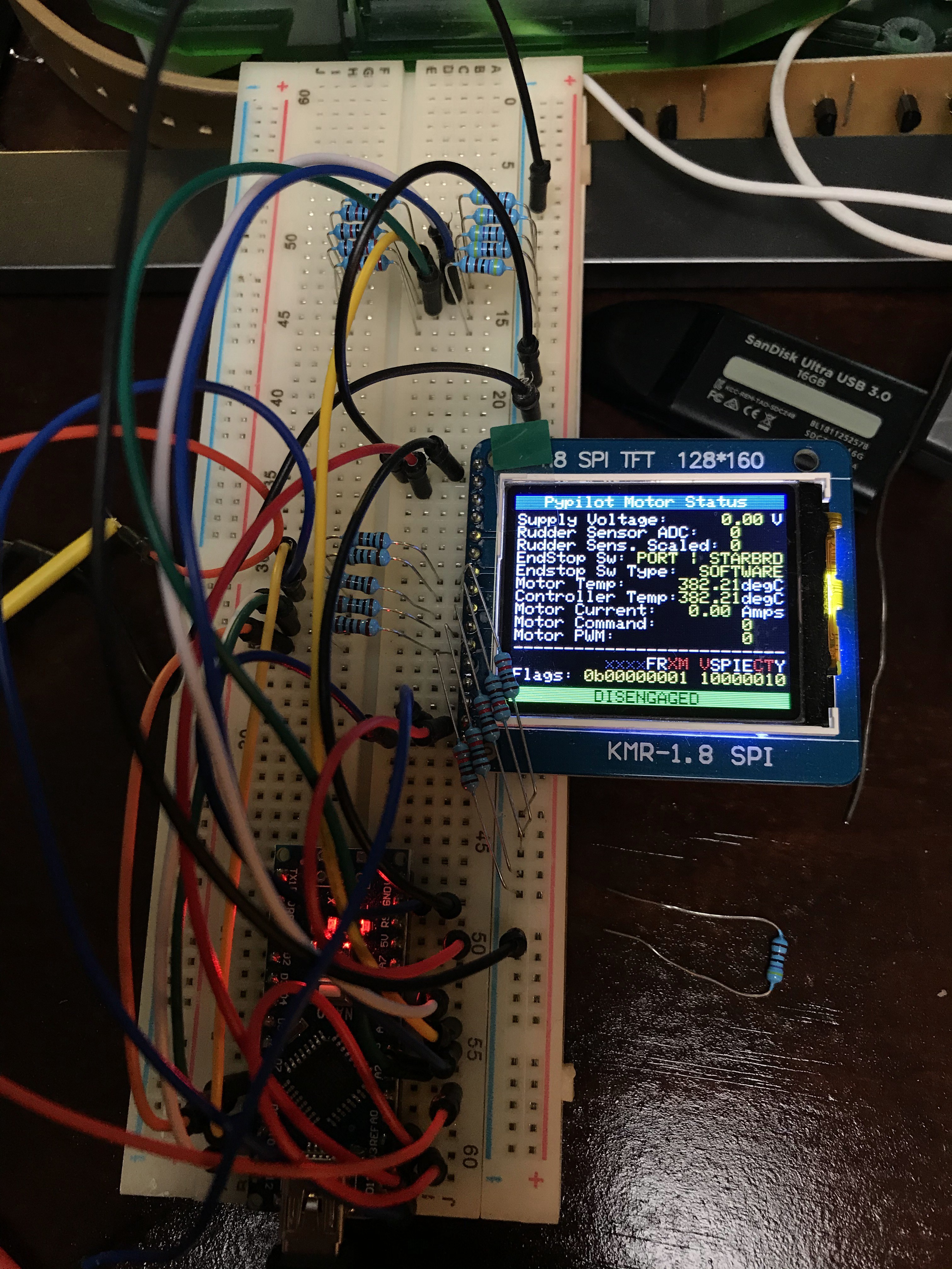
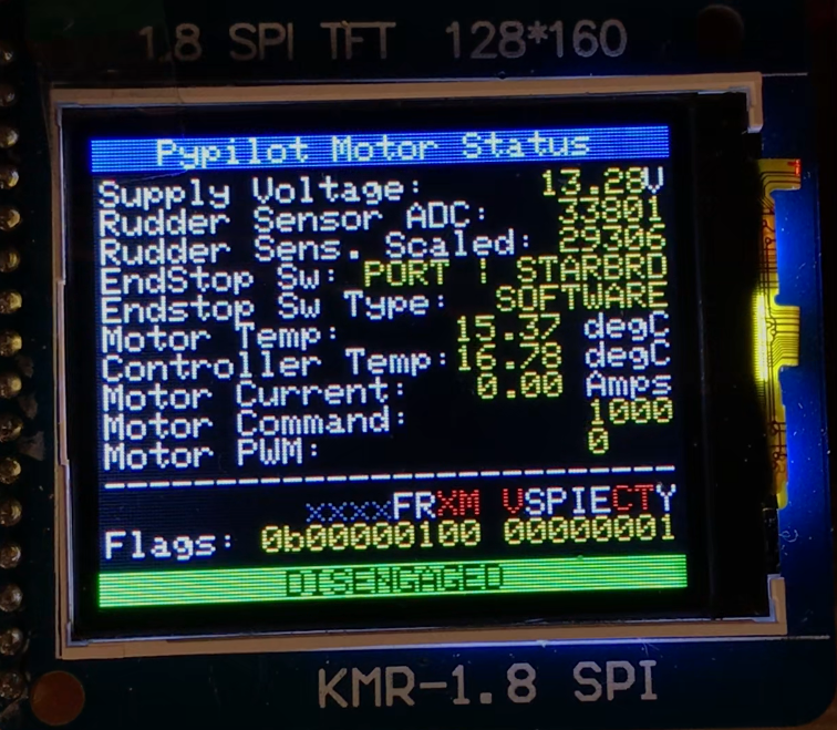
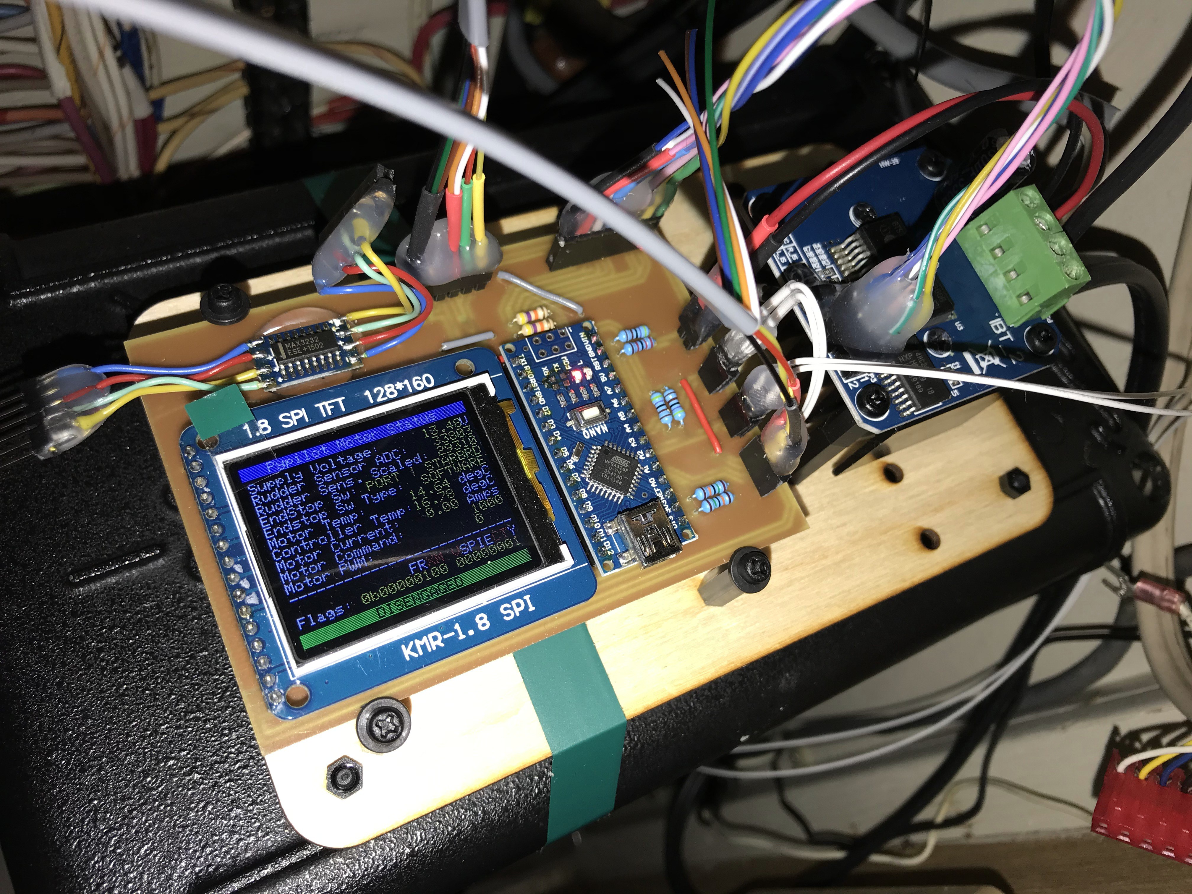
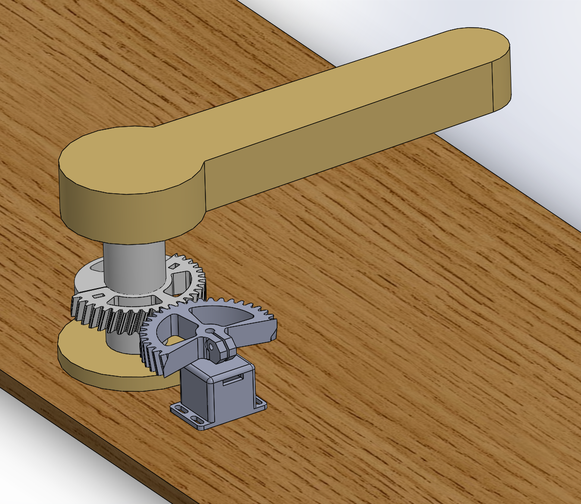
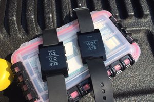
This is the a two part project: One is the very simple: How to install and configure OpenPlotter to be used with OpenCPN for charts with compass and GPS and PyPilot for basic autopilot functionality with waypoint tracking. The other is me re-engineering the motor.ino motor controller code to get it into a serviceable form. I also added a nice status display.
Here is my code: https://github.com/McNugget6750/pypilot/tree/master/arduino/motor
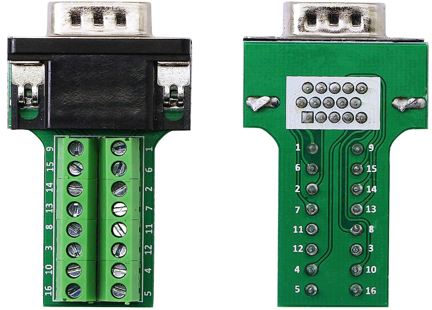
Here are the schematics and the board: https://github.com/McNugget6750/pypilot-motor-electronics


 Brook Patten
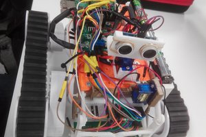
 Alan Chambers
 pastcompute
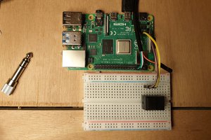
We are thankful to you, It become helpful for us in solving the problem of my client site http://www.unlimitedapks.com/