 Timo Birnschein
When things are not so easy...
I ran into a trouble when I tried to understand what was required to get the motor controller to PyPilot to work. I thought, it should be easy to just hook up an Arduino to an H-bridge that you can easily obtain from Amazon or Ebay and have the system communicate happily. However, I ran into documentation issues right from the start, couldn't find a part-list, couldn't find schematics and so on and so forth.
Turns out code and schematics are available but it took me the better part of a week to understand what's going on in the arduino code and I didn't like the schematics.
Please do not get me wrong: What the original author, Sean, put together is amazing overall! But the motor controller, which was specifically designed to run a bare metal H-bridge at 16khz by doing bit banging on the Arduino, left much to be desired in terms of ease of use and serviceability. So I rewrote major parts of it and restructured others and I hope, this version is a bit easier to understand and to get to work.
Yes, I am aware of the "not invented here" principle but I also strongly believe in opensource and feel like I did contribute to the overall scheme of things by putting this together and publishing what I have learned in the process.
Let's talk about parts:
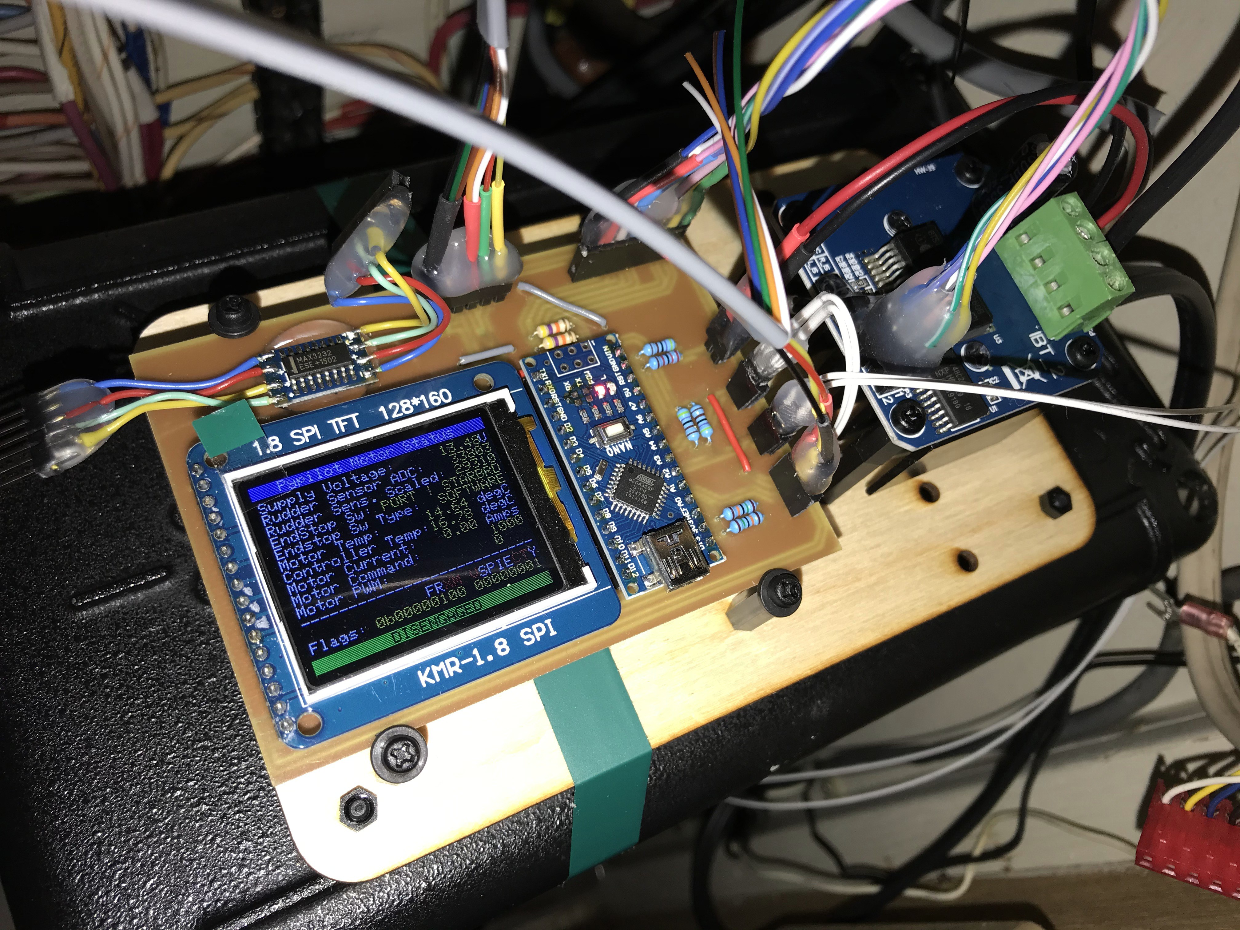
- IBT_2 fully integrated and protected H-Bridge I found to be very powerful and reliable so far
- Arduino Nano Clone
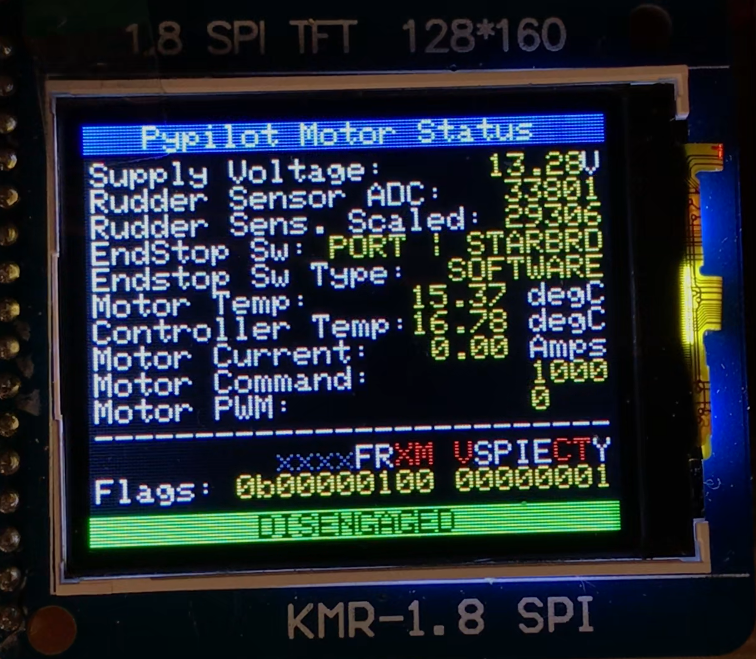
- 160x128 pixel TFT display
- Two NTC 100k thermocouples you would just order for your 3D printer
- A 5Kohm potentiometer as a rudder sensor
- Couple wired resistors to make a single sided board possible
- Some pin headers
- Several 3d printed parts
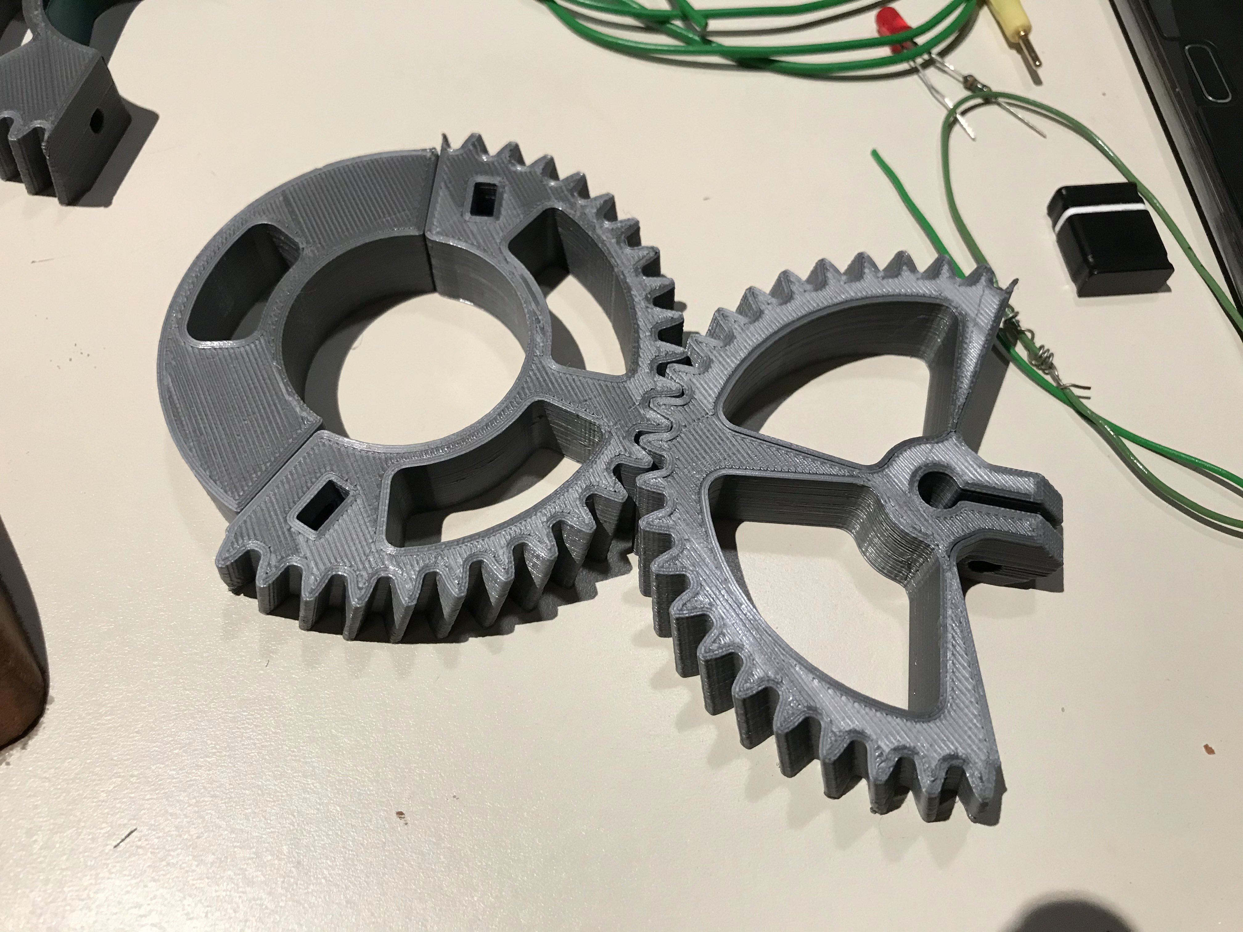
The parts above are for my rudder sensor. The gear on the left clamps around one of my two rudders, the gear on the right is bolted straight to my 5K poti.
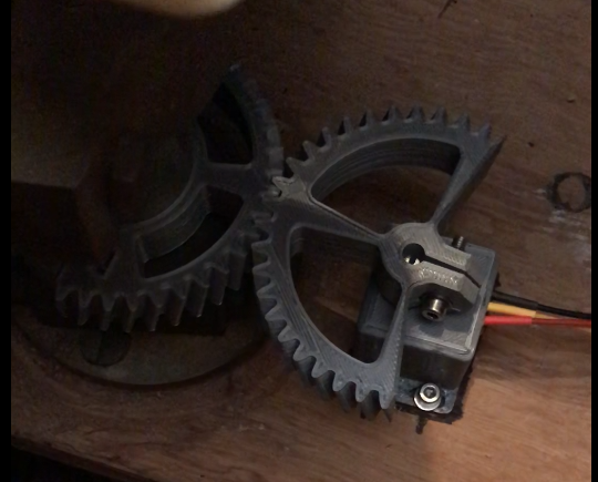
This gives me a really nice rudder position feedback which is used for telemetry and to let PyPilot know that it shouldn't push into the MAX and MIN any longer using the rudder actuator.
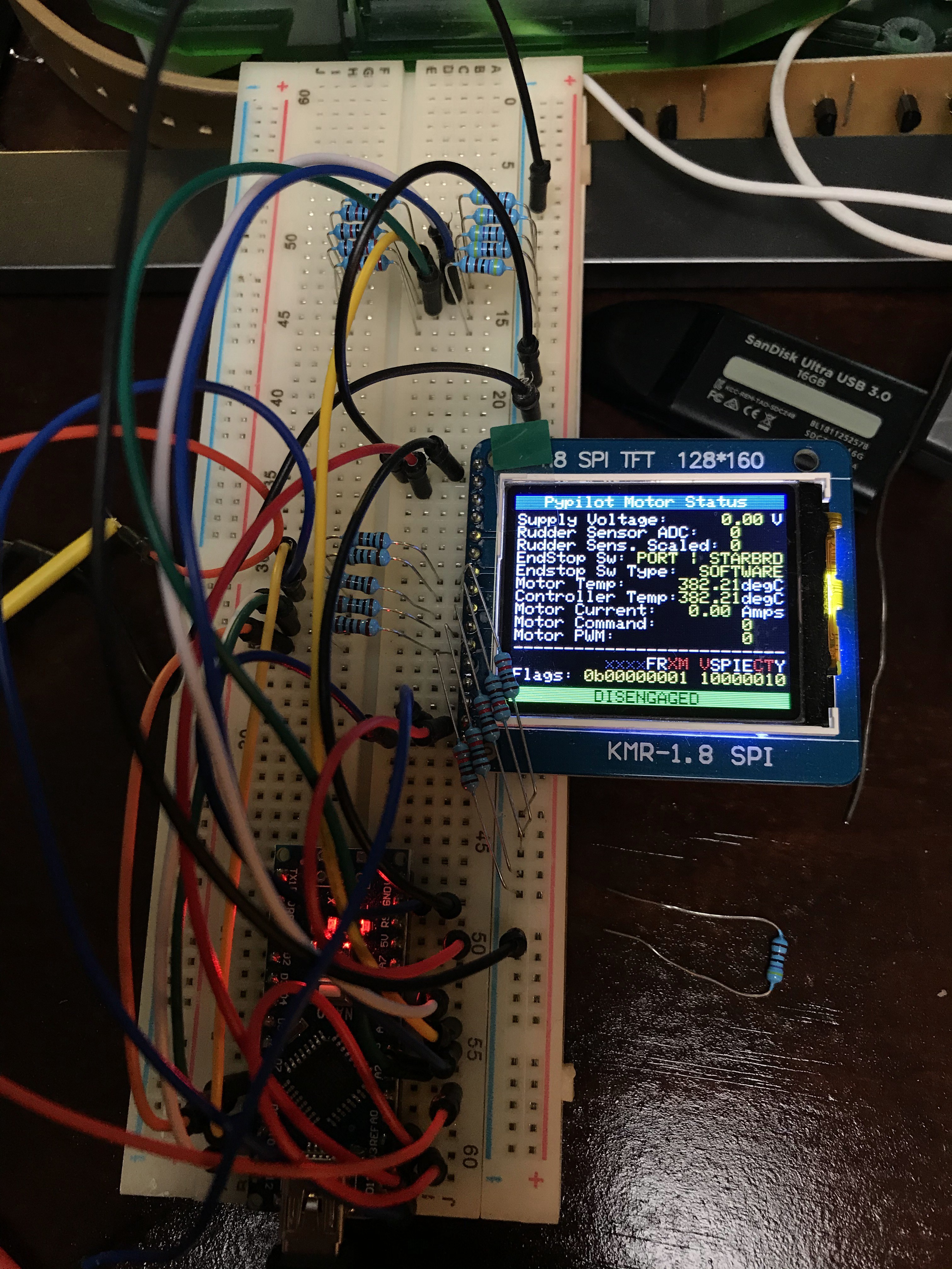
As with many other projects, I usually start with a breadboard. I like having a display to be able to quickly debug the system. Like in this case, the uart port is already in use to communicate with PyPilot and cannot easily be repurposed for debugging. So I added the super high performance TFT library ST7735 to my sketch and added the display functionality.
Now I needed to put everything into one device instead of flying wires and bread boards since I wanted a more permanent installation.
I used KICad to create schematics for the board and created a layout for a single sided, easy to make at home PCB which I then milled out on me $200 PCB mill that I still love to death:

The code for this motor controller branch can be found on my github page.
The motor controller code is located under Arduino/Motor/Motor.ino. Please let me know if you have any issues with the code. Please keep in mind that you will need the display library, unless you deactivate the display in the config.h header file.
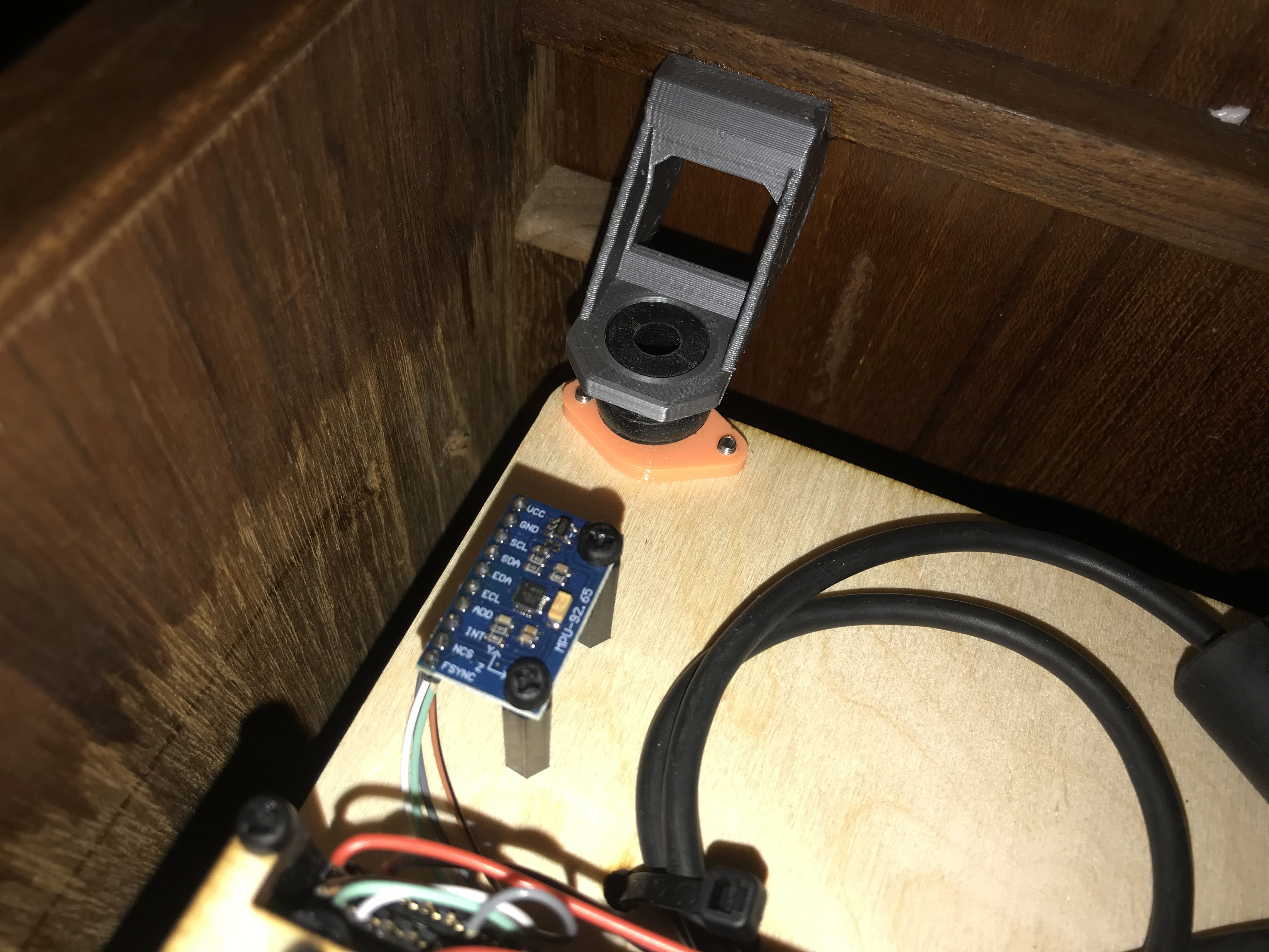
On the Raspberry Pi 3 side, the implementation looks as follows. I integrated it into one of two helms using rubber dampeners that one would usually use for vibration isolation on camera gimbals and the like.
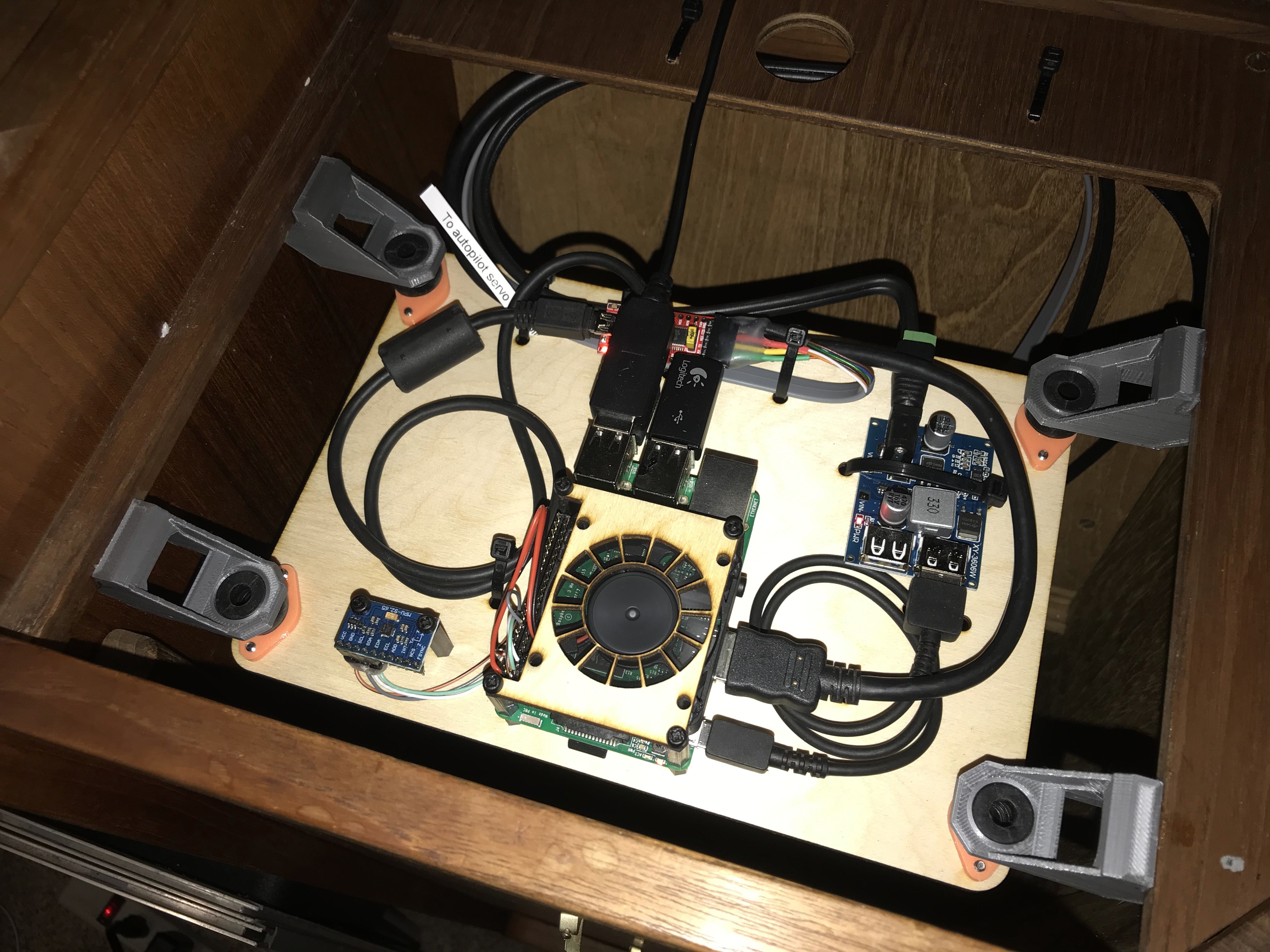
As a power supply, I used a 12V to 5.2V high speed charging circuit. This thing is definitely able to drive the PI3 under load with no issues without showing the dreaded low power warning.
Discussions
Become a Hackaday.io Member
Create an account to leave a comment. Already have an account? Log In.
Em tentando montar o controlador do motor, poderia mandar o esquema dos pinos, facilitaria muito
Are you sure? yes | no
Hey! Im also trying to use the same cheap h-bridge for pypilot motor controller and I'm glad I found your page! Nice work! What is that usb-serial adapter you are using? I bought some cheap ones (blue transparent housing) and I cant get the nmea connection to work.
Are you sure? yes | no