0%
0%
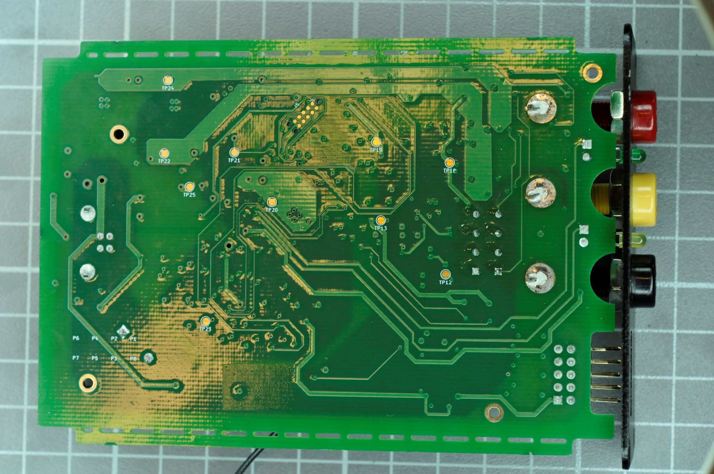
Teardown ZS-2102-A
As I actually had the chance to use and test this device, i couldn't resist to open it.
 Tom
TomBecome a Hackaday.io member
Already have an account? Log in.
Just one more thing
To make the experience fit your profile, pick a username and tell us what interests you.
Pick an awesome username
hackaday.io/
Your profile's URL: hackaday.io/username. Max 25 alphanumeric characters.
Pick a few interests
Projects that share your interests
People that share your interests
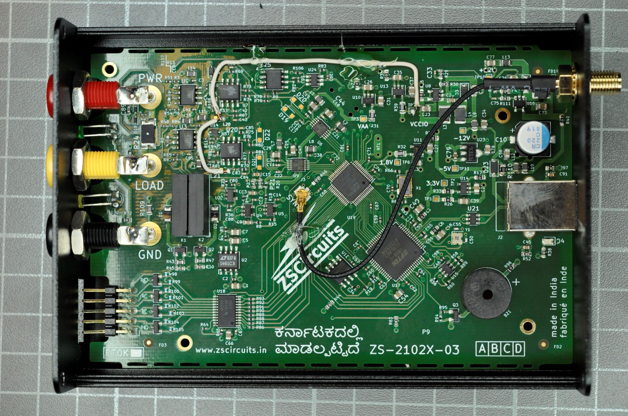
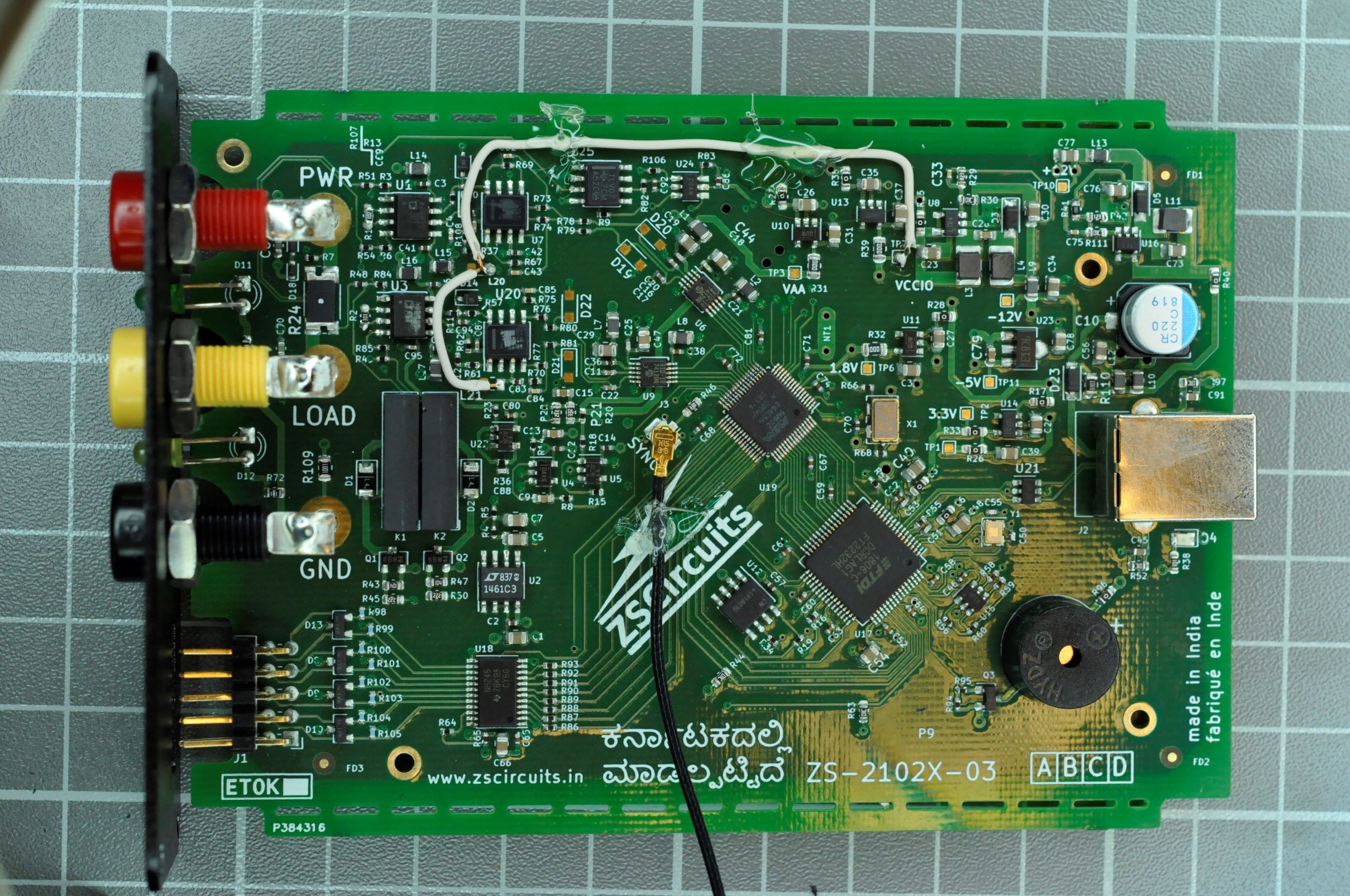
 Using a microscope i was able to read the part numbers of the burnished components. You find a list of the key components in the components list!

 Sagar 001
 Tavish Naruka
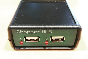
 Max
Max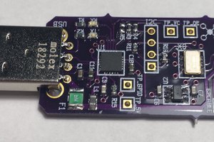
 Carbon
regrading the banana connectors.
i usually use the multicontact (stäubli) banana connectors, yes they are more expensive but i think the highest quality banana connectors