 Kara Abdelaziz
Simulation
First of all was the simulation, everything was done primary on Logisim to fully understand how Gigatron works, and to test if it is possible to implement the different modifications. 3 different simulations were done on Logisim that can be downloaded below or on Github:
- first is Gigatron.circ used primarely for acadimic and teaching purposes, it is a simplified logic version of Gigatron, in whitch the 74 series were not used, but a simplified logical equivalents were utilized instead. This version is stuffed with debugging and monitoring mechanisms.
- second is GigatronTTL.circ is a more accurate simulation were the same 74 series logic chips were used, nevertheless some parts in Gigatron can not be simulated under Logisim due to their analogic nature, like resistrors/diods grid used in the Control Unit (UC), they were replaced by some logic ccircuits equivalent. Also, in some situations Gigatron mixed up the bits order in some registers, for clarity the simulation holds the natural order of bits.
- third MegatronTTL.circ, an accurate simulation of Megatron using 74 series chips.
For the simulation to work properly, GigatronTTL.circ and MegatronTTL.circ needs in the same directory 74xx Library.circ file to work. Also MegatronTTL.circ needs that the 3 ROMs (27c512) under CU circuit must be loaded consecutively from up to down with CU-datapath.ROM, CU-registers.ROM, CU-ALU.ROM in the case where that was not done automatically.
Two proof-of-concept programs can be executed on both Gigatron and Megatron, Fibonacci and Factorial programs. To execute them, the binary machine code of one of them must be loaded in the ROM of the machine, the binary machine code for Fibonacci is saved in Fibonnaci.ROM file and Factorial is saved in Factorial.ROM file. Two other files, Fibonnaci.txt and Factorial.txt are used to contain the assembly language for the two programs, mainly for explaining them.
Both programs have input values for execution, the input value (example 3) has to be put inside the register BUS-IN in Gigatron, and KEYBOARD-IN in Megatron, IOC register also in Megatron must contain 0x11 (or 00010001b) to choose the keyboard to be the primary input device. The result of the programs is shown in output register at the end of the execution. Step-by-step execution can also be done by using the mode "manual" of the clock, all the componants informations can be monitored by the associated 7 display segments, plus the contents of the RAM by show it's appropriate window.
Modifications
The modifications done upon Megatron in comparison to Gigatron are mainly intended to reduce the number of components for the ease of use and implementation, and secondly to enhance some hardware aspects, like to bring more flexibility for adding and managing more devices.
The list of all the modifications done to Megatron is as below :
- Removing the VGA and replacing it by small more intelligent handheld screens, with higher resolution and higher color depth. In fact the VGA imposes some heavy constraints to the architecture, like most of the time spent by Gigatron is for rendering VGA signals, and the constraint to use 6.25 MHz clock, which (i guess) leaded to apply a non desirable pipeline, and some additional hardware non trivial manipulation to comply timing constraints.
- Removing the pipeline.
- Doubling the RAM capacity from 32 KB to 64 KB.
- Using 74181 ALU to have faster arithmetic/logic calculation and to reduce the number of chips.
- Replacing the CU (Control Unit) complex logic by 3 ROMs (used like look-up tables), which leads to a smaller simpler circuit and more flexible programmable Control Unit.
- Adding a proper Input/Output Unit implementing a real device manager allowing the addition of more input and output devices.
- Adding a native keyboard to Megatron and potentially other devices.
Software
Some additions are made to the Instructions Set, especially the instructions responsible for the Input/Output Unit, more details...
Read more »
 Blair Vidakovich
 John Sully
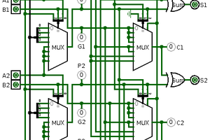
 Squonk42
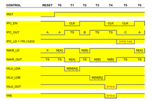
 agp.cooper
to Courtney.
Sorry I was busy at work.
<<Yes, it would be easier to get others involved if they can see everything, and what is proposed or built. I don't know what diagramming software or sites for that are out there. I see all the diagrams that some post, but don't know how they make them. I am not going to sit in Paint and make this stuff. My art skills are not that good. >>, most of the time I am using Logisim for diagrams and simulation, but you can also use this drawing online tool at www.draw.io website, I am using it a lot.
<<I'd need to gains some tools, resources, and skills to do this. I've never worked with SMT. I might want to invest in a flow oven or similar. And I just hope I don't have to work with BGAs. Even SOICs are a bit daunting. And going that far, I might need a microscope too (and new glasses).>>, That real a big problem, also for me I am not an electronic engineer my self, but referring to some electronicians, the problem is not that big, you can charge at some point someone else to do the electronics, or you can take certain time to learn.
<<I think Power/Exp might be handy to add. I'm not sure about SqrRt. I mean, I am not quite up to doing IEEE floating-point. Maybe fixed point, but can't really do that past a fractional part more precise than 1/256.>>, if you are really thinking of using a fixed point solution, one way to do it is to implement for each operation 2 type, one returning the real result and the other the fractional part, in my sense, it would be more manageable.
<<So, a battery, supercapacitor, or flash could help preserve the index into the random count.>>, I think a simple, small serial flash memory could do the trick too.
<<For instructions, it would be nice to have native instructions for most BASIC commands. However, things like ASC, Char, Val, etc., would likely not be good for a Harvard machine as native instructions. I don't see any real way to do those instructions outside of using microcode or software.>>, personally, I would implement them like a normal functions.
<<I had another brainstorm. What if the bootstrap/reset unit were to run the system ROM through the decoder ROMs on boot and then cache that into SRAMs?>>, by the system ROM and decoder ROM you mean program ROM and Control Unit ROM, if so? I don't know if that would work, but you will face a problem with the control signals, normally you will need a lot of them, plus the data and instruction output.