 Yannis
In the last post I covered improvements in the hardware side of Tinymovr R3.1 that resulted in a minor revision R3.2. This post will go over improvements on the Tinymovr firmware performed in the past couple months.
CAN Bus Protocol
Implementation of CAN communication is now complete, and Tinymovr is fully operable through CAN. In the protocol I designed I’ve decided to stay as close as possible to the CANSimple protocol, adopted by the ODrive community, for compatibility reasons. Of course, it was not possible to fully conform to that protocol, as there are differences in hardware and features. However, in the approach I've taken I've tried to match the functionality of critical CAN commands (such as setting of states, setpoints and parameters). In addition, in order to stay compatible I've tried to extend the message content of some commands, instead of replacing; for instance, the State endpoint (0x03) returns an array that contains the error as a first element but also the controller state and control mode. If you are interested in the error only, you can just grab the first item in the returned tuple.
Below is a table with the commands (endpoints) in more detail:
| Endpoint | Address | Type | Values | Byte Offset |
| Estop | 0x02 | W | -- | -- |
| State | 0x03 | R | Error (uint8) State (uint8) Ctrl Mode (uint8) | 0 1 2 |
| CAN Config | 0x05 | R | CAN ID (uint8) kbaud Rate (uint16) | 0 1 |
| Set CAN Config | 0x06 | W | CAN ID (uint8) kbaud Rate (uint16) | 0 1 |
| Set State | 0x07 | W | State (uint8) Control Mode (uint8) | 0 1 |
| Encoder Estimates | 0x09 | R | Position Estimate(float) Velocity Estimate(float) | 0 4 |
| Set Position Setpoint | 0x0C | W | Position Setpoint (float) Velocity FF (int16) Current FF (int16 | 0 4 6 |
| Set Velocity Setpoint | 0x0D | W | Velocity Setpoint (float) Current FF (float) | 0 4 |
| Set Current Setpoint | 0x0E | W | Current Setpoint (float) | 0 |
| Set Limits | 0x0F | W | Velocity Limit (float) Current Limit (float) | 0 4 |
| Iq Estimate and Setpoint | 0x14 | R | Iq Estimate (float) Iq Setpoint (float) | 0 4 |
| Limits | 0x15 | R | Velocity Limit (float) | 0 4 |
| Reset | 0x16 | W | -- | -- |
| Vbus | 0x17 | R | Bus Voltage (float) | 0 |
| Position and Velocity Gains | 0x18 | R | Position Gain (float) Velocity Gain (float) | 0 4 |
| Set Position and Velocity Gains | 0x19 | W | Position Gain (float) Velocity Gain (float) | 0 4 |
| Device Info | 0x1A | R | Device info register (uint32) | 0 |
| MCU Cycle Timings | 0x1B | R | Busy Cycles (uint16) Total Cycles (uint16) | 0 2 |
| Save Config | 0x1C | W | -- | -- |
| Erase Config | 0x1D | W | -- | -- |
| Motor Info | 0x1E | R | Motor Calibrated (uint8) Motor R (uint16) Motor Pole Pairs (uint8) Motor L (float) | 0 1 3 4 |
The endpoints that are read (R) work by the client sending a request to transmit (RTR) and Tinymovr sending back the corresponding message. Note that this is an early protocol draft, and subject to change.
Position Tracking Improvements
The encoder/observer infrastructure has been vastly improved as well. Here, I’ve been dealing with the problem of diminishing floating point accuracy as the position setpoints reach large values, due to the limited 23-bit significand of single precision floats. This is an issue that has come up from time to time in various message boards, but afaik no concrete solution is available up till now.
To address this issue, there are two sub-problems that need to be addressed: The first problem concerns the estimation of the rotor angle in order to derive electrical angle and ensure accurate commutation. This is easily achieved by using a separate angle estimate that is wrapped to [0, 2pi). The second problem is a bit more complex and entails accurately tracking the rotor position value on the position axis. The issue here is that at large values the estimate of rotor position is increasingly quantized, due to the rapidly diminishing accuracy of floating point representation. Consider as an example the value 5000000 (5*10^6), which is a representable number in IEEE 754 single-precision floating point variable format. The next representable number, is 5000000.5. This is barely adequate to represent the observer rotor position estimate, and it only gets worse as the values increase. In tests that I did at such rotor positions, the effect due to quantization is that the velocity estimate has a greater variance than in values close to zero.
One way of fixing this is to use double-precision floats. While offering a greater high-precision position range, this is still not an ideal solution as it still suffers from diminishing precision in large values. The diagram below borrowed from Wikipedia illustrates precision for single and double precision IEEE754 floating point values:

It is evident that there is great variation in precision along the value axis. Accurate encoder positioning does not need more than a few decimal digits, however the floating point format "concerntrates" much precision to areas near zero.
Instead of using double precision floats, the solution I went ahead with is based on a composite scheme that divides the position axis into intervals. In this scheme, two values are used in order to represent a rotor position: one is a 32-bit integer , within which a single-precision float represents the offset of the motor from the middle of the interval. The diagram below gives an idea of the scheme:
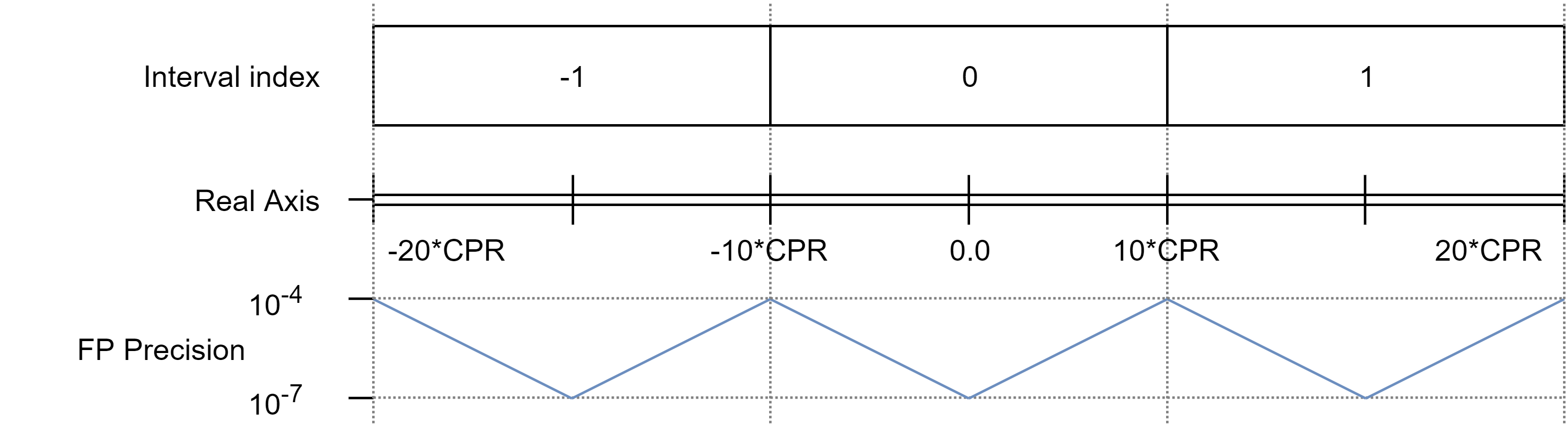
Note that FP Precision values are estimates based on the previous diagram. This has vastly improved precision of estimated position tracking performance throughout the position axis.
An important issue that this development addresses is with velocity controlled motors that are left running for a long time at high velocities, such as wheeled robots or spindles. With the original, single precision positioning scheme, variance of velocity estimates would increase the further away from zero the position gets, which would translate in more noisy motor behavior.
With the new positioning scheme, it should be possible to command any reasonable velocity value and not worry about tracking accuracy (since precision is mostly constant throughout the axis) or position overflow. As an illustrative figure, we may look at the time it takes for a motor position value to overflow at constant angular velocity. Let us consider an interval half-length of 10 * CPR (the MA702 sensor has a max resolution of 12,5 bits, which can be increased to 13bits through the observer, so 10 * 2^13 = 81920), and a rotational velocity of 10000 RPM. Under these assumptions, the time before position overflow would occur is:
81920 * 2^31 / 8192 / 10000 / 60 / 24 / 365 = 4.0857 years
So four years spinning at 10000 rpm with mostly constant multi-digit precision throughout the position axis. Yeah, bearings will have probably worn out to bits and shorted the electronics by that time :D
Note that the above does not change the precision of commanded position *setpoints*; these still have single-precision accuracy, with all of it's precision drawbacks. However, what the new scheme guarantees is that no matter what the setpoint is, it will be tracked accurately.
In addition, this currently does not affect the values returned via the CAN interface; these are still converted to float. However, I'm planning the addition of endpoints to access the precise position values.
Quadruped Robot
On other news: I've completed the quadruped robot construction and a series of tests is on the way. Below the robot in "initialization" pose:
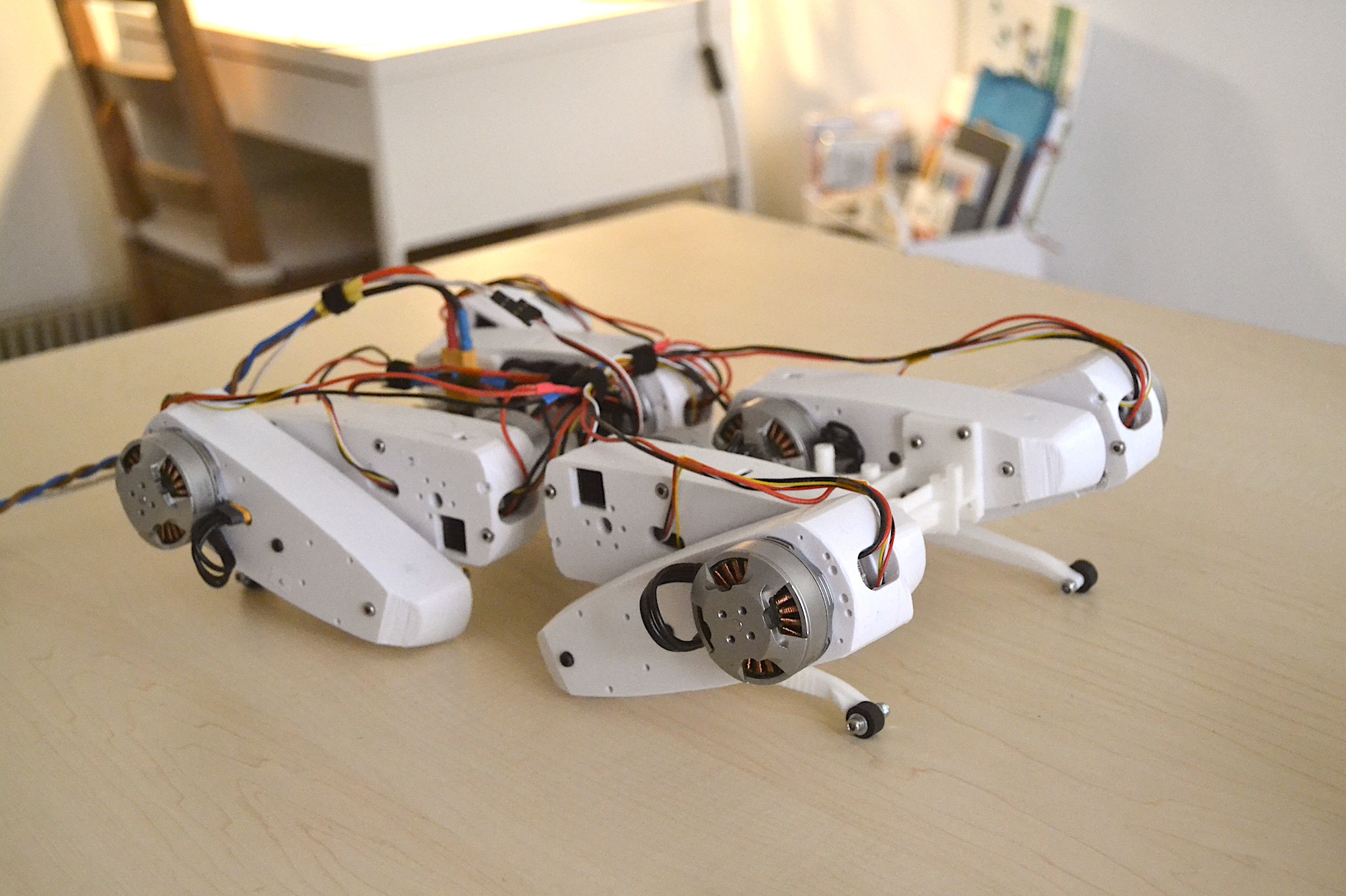
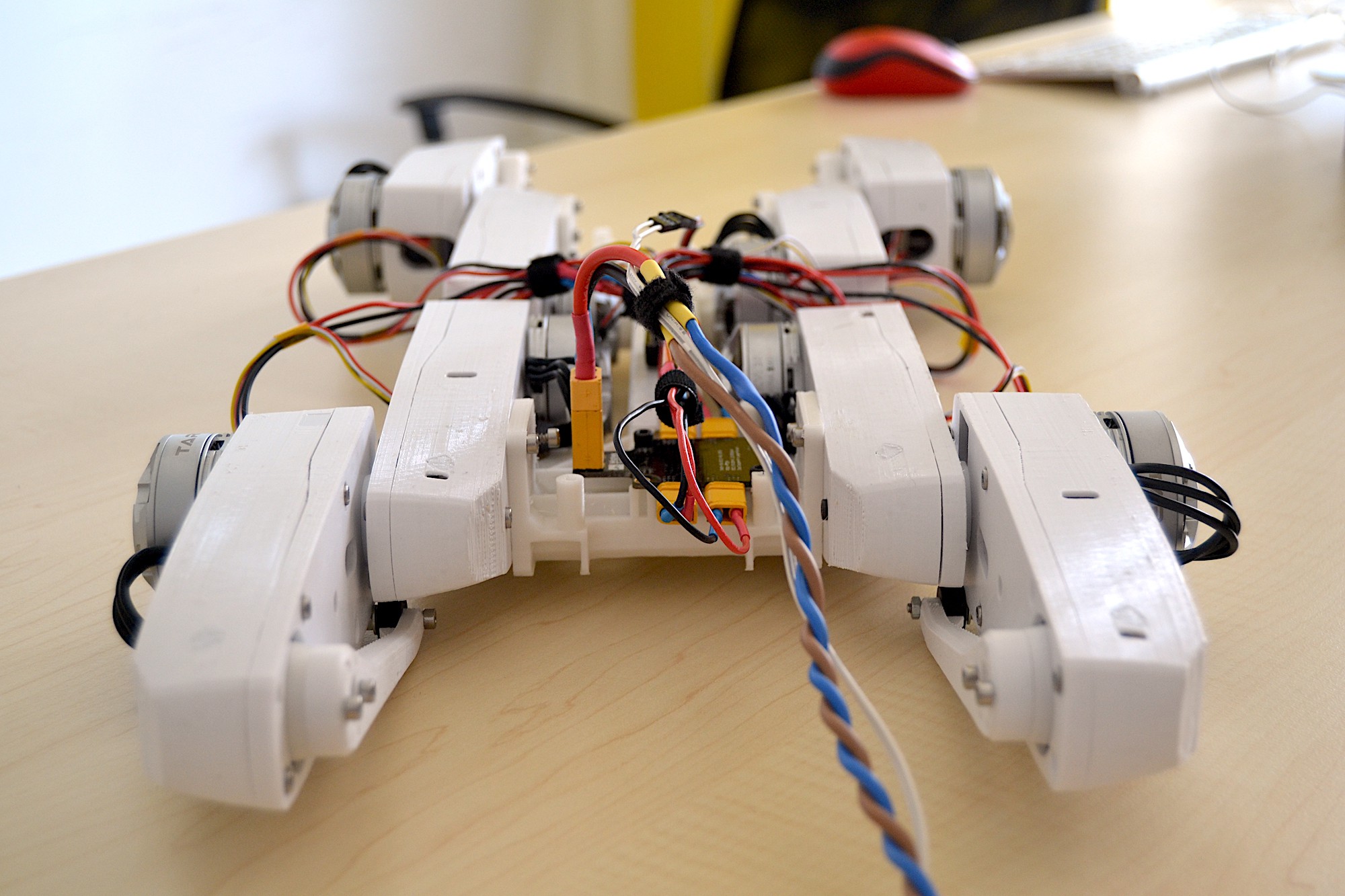
The robot is 8DOF (so no holonomic motion yet), and carries 8x Tinymovr boards embedded in the legs. In it's current state it has off-board power supply and control and no IMU. I'll be gradually integrating those on-board over the next iterations. The robot weights just 1.8 kilograms (around 4 pounds), which is expected to rise to 1.9-2.0 kg together with a Raspberry pi and small battery.
That's all for now. I've mentioned it a few times :D but eventually in the next post I'll have more information on the availability of Tinymovr R3.2 boards (the latest revision that addresses some power supply issues outlined in the previous post), so stay tuned!
Discussions
Become a Hackaday.io Member
Create an account to leave a comment. Already have an account? Log In.