Yannis
-
Firmware improvements - CAN Protocol, Improving Position Tracking
06/13/2020 at 20:06 • 0 commentsIn the last post I covered improvements in the hardware side of Tinymovr R3.1 that resulted in a minor revision R3.2. This post will go over improvements on the Tinymovr firmware performed in the past couple months.
CAN Bus Protocol
Implementation of CAN communication is now complete, and Tinymovr is fully operable through CAN. In the protocol I designed I’ve decided to stay as close as possible to the CANSimple protocol, adopted by the ODrive community, for compatibility reasons. Of course, it was not possible to fully conform to that protocol, as there are differences in hardware and features. However, in the approach I've taken I've tried to match the functionality of critical CAN commands (such as setting of states, setpoints and parameters). In addition, in order to stay compatible I've tried to extend the message content of some commands, instead of replacing; for instance, the State endpoint (0x03) returns an array that contains the error as a first element but also the controller state and control mode. If you are interested in the error only, you can just grab the first item in the returned tuple.
Below is a table with the commands (endpoints) in more detail:
Endpoint Address Type Values Byte Offset Estop 0x02 W -- -- State 0x03 R Error (uint8)
State (uint8)
Ctrl Mode (uint8)0
1
2CAN Config 0x05 R CAN ID (uint8)
kbaud Rate (uint16)0
1Set CAN Config 0x06 W CAN ID (uint8)
kbaud Rate (uint16)0
1Set State 0x07 W State (uint8)
Control Mode (uint8)0
1Encoder Estimates 0x09 R Position Estimate(float)
Velocity Estimate(float)0
4Set Position Setpoint 0x0C W Position Setpoint (float)
Velocity FF (int16)
Current FF (int160
4
6Set Velocity Setpoint 0x0D W Velocity Setpoint (float)
Current FF (float)0
4Set Current Setpoint 0x0E W Current Setpoint (float) 0 Set Limits 0x0F W Velocity Limit (float)
Current Limit (float)0
4Iq Estimate and Setpoint 0x14 R Iq Estimate (float)
Iq Setpoint (float)0
4Limits 0x15 R Velocity Limit (float) 0
4Reset 0x16 W -- -- Vbus 0x17 R Bus Voltage (float) 0 Position and Velocity Gains 0x18 R Position Gain (float)
Velocity Gain (float)0
4Set Position and Velocity Gains 0x19 W Position Gain (float)
Velocity Gain (float)0
4Device Info 0x1A R Device info register (uint32) 0 MCU Cycle Timings 0x1B R Busy Cycles (uint16)
Total Cycles (uint16)0
2Save Config 0x1C W -- -- Erase Config 0x1D W -- -- Motor Info 0x1E R Motor Calibrated (uint8)
Motor R (uint16)
Motor Pole Pairs (uint8)
Motor L (float)0
1
3
4The endpoints that are read (R) work by the client sending a request to transmit (RTR) and Tinymovr sending back the corresponding message. Note that this is an early protocol draft, and subject to change.
Position Tracking Improvements
The encoder/observer infrastructure has been vastly improved as well. Here, I’ve been dealing with the problem of diminishing floating point accuracy as the position setpoints reach large values, due to the limited 23-bit significand of single precision floats. This is an issue that has come up from time to time in various message boards, but afaik no concrete solution is available up till now.
To address this issue, there are two sub-problems that need to be addressed: The first problem concerns the estimation of the rotor angle in order to derive electrical angle and ensure accurate commutation. This is easily achieved by using a separate angle estimate that is wrapped to [0, 2pi). The second problem is a bit more complex and entails accurately tracking the rotor position value on the position axis. The issue here is that at large values the estimate of rotor position is increasingly quantized, due to the rapidly diminishing accuracy of floating point representation. Consider as an example the value 5000000 (5*10^6), which is a representable number in IEEE 754 single-precision floating point variable format. The next representable number, is 5000000.5. This is barely adequate to represent the observer rotor position estimate, and it only gets worse as the values increase. In tests that I did at such rotor positions, the effect due to quantization is that the velocity estimate has a greater variance than in values close to zero.
One way of fixing this is to use double-precision floats. While offering a greater high-precision position range, this is still not an ideal solution as it still suffers from diminishing precision in large values. The diagram below borrowed from Wikipedia illustrates precision for single and double precision IEEE754 floating point values:
![]()
It is evident that there is great variation in precision along the value axis. Accurate encoder positioning does not need more than a few decimal digits, however the floating point format "concerntrates" much precision to areas near zero.
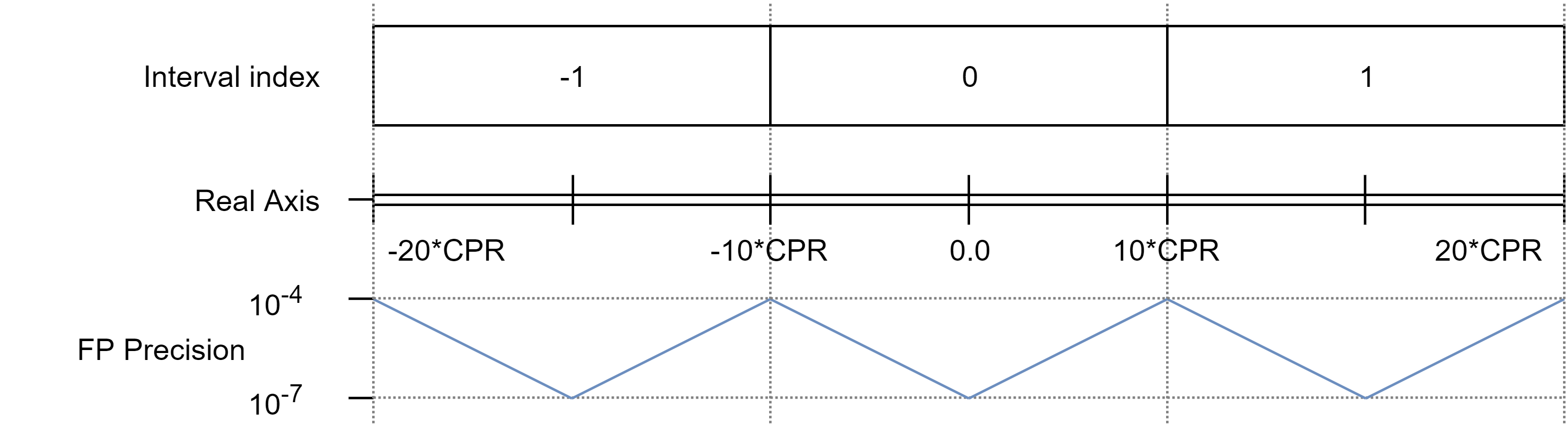
Instead of using double precision floats, the solution I went ahead with is based on a composite scheme that divides the position axis into intervals. In this scheme, two values are used in order to represent a rotor position: one is a 32-bit integer , within which a single-precision float represents the offset of the motor from the middle of the interval. The diagram below gives an idea of the scheme:
![]()
Note that FP Precision values are estimates based on the previous diagram. This has vastly improved precision of estimated position tracking performance throughout the position axis.
An important issue that this development addresses is with velocity controlled motors that are left running for a long time at high velocities, such as wheeled robots or spindles. With the original, single precision positioning scheme, variance of velocity estimates would increase the further away from zero the position gets, which would translate in more noisy motor behavior.
With the new positioning scheme, it should be possible to command any reasonable velocity value and not worry about tracking accuracy (since precision is mostly constant throughout the axis) or position overflow. As an illustrative figure, we may look at the time it takes for a motor position value to overflow at constant angular velocity. Let us consider an interval half-length of 10 * CPR (the MA702 sensor has a max resolution of 12,5 bits, which can be increased to 13bits through the observer, so 10 * 2^13 = 81920), and a rotational velocity of 10000 RPM. Under these assumptions, the time before position overflow would occur is:
81920 * 2^31 / 8192 / 10000 / 60 / 24 / 365 = 4.0857 years
So four years spinning at 10000 rpm with mostly constant multi-digit precision throughout the position axis. Yeah, bearings will have probably worn out to bits and shorted the electronics by that time :D
Note that the above does not change the precision of commanded position *setpoints*; these still have single-precision accuracy, with all of it's precision drawbacks. However, what the new scheme guarantees is that no matter what the setpoint is, it will be tracked accurately.
In addition, this currently does not affect the values returned via the CAN interface; these are still converted to float. However, I'm planning the addition of endpoints to access the precise position values.
Quadruped Robot
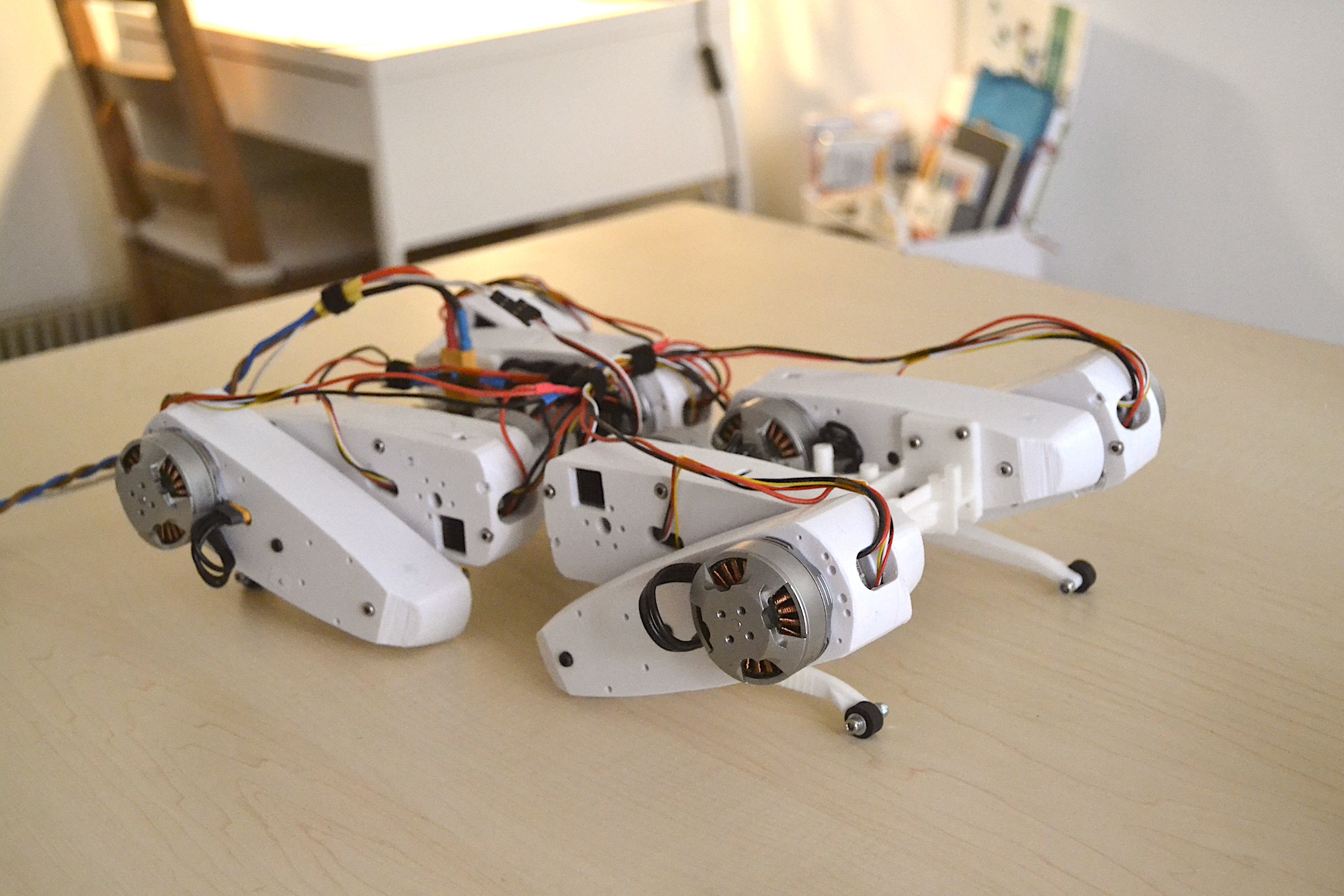
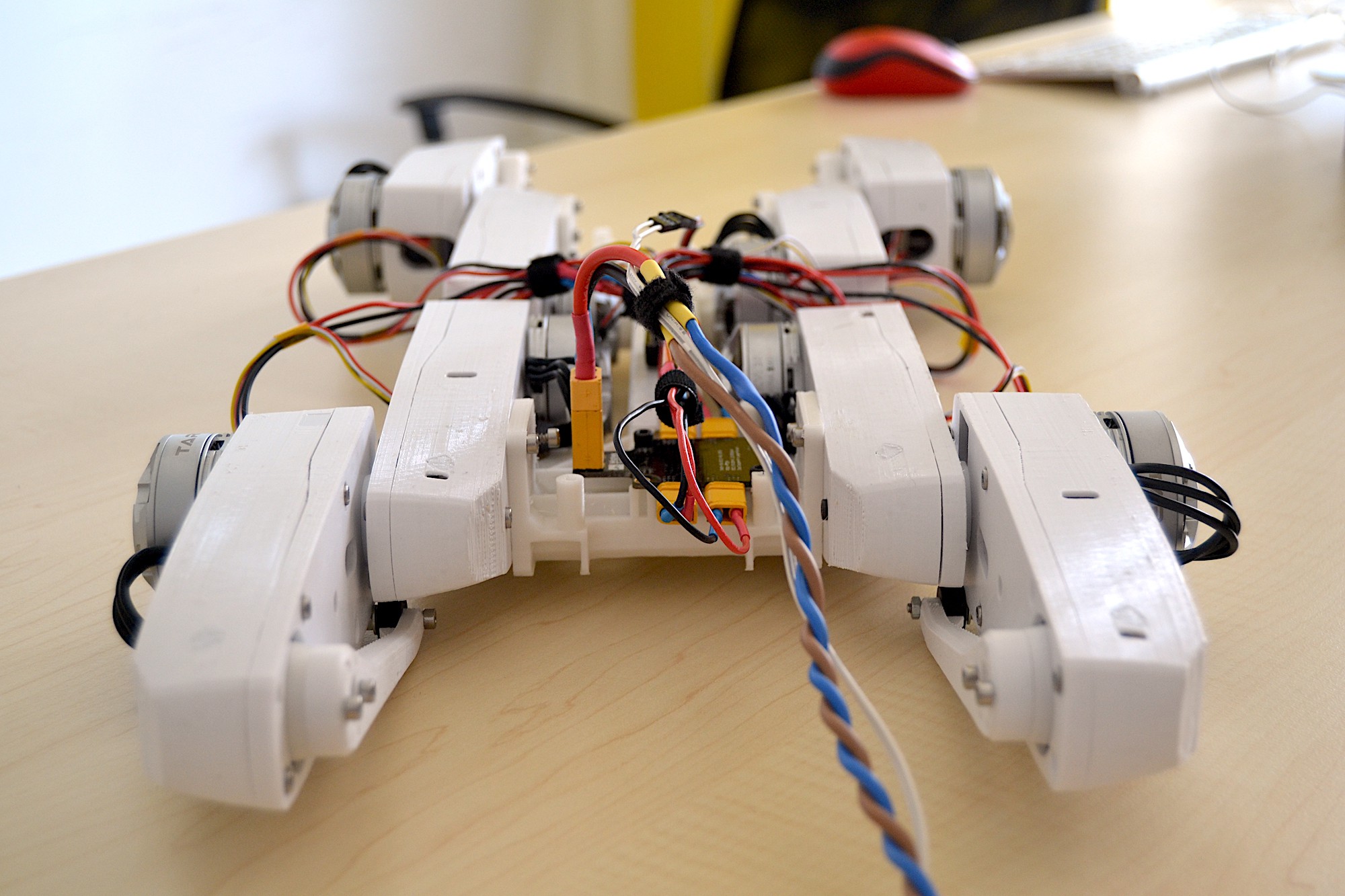
On other news: I've completed the quadruped robot construction and a series of tests is on the way. Below the robot in "initialization" pose:
![]()
![]()
The robot is 8DOF (so no holonomic motion yet), and carries 8x Tinymovr boards embedded in the legs. In it's current state it has off-board power supply and control and no IMU. I'll be gradually integrating those on-board over the next iterations. The robot weights just 1.8 kilograms (around 4 pounds), which is expected to rise to 1.9-2.0 kg together with a Raspberry pi and small battery.
That's all for now. I've mentioned it a few times :D but eventually in the next post I'll have more information on the availability of Tinymovr R3.2 boards (the latest revision that addresses some power supply issues outlined in the previous post), so stay tuned!
-
Dealing with (and fixing) an unexpected glitch
05/31/2020 at 12:23 • 0 commentsIn this post I wanted to focus on Tinymovr firmware improvements and plan out the next steps, however an unexpected glitch had me spending all my development time on it and thus the rest of the updates have been pushed back a bit.
Last week I put together a “torture test” for Tinymovr with the aim of testing several aspects such as position tracking, torque generation, commutation in higher angular velocities, communication etc. The test consisted of reading encoder estimates and commanding random position increments ranging from 0 to 2π (0 to 8192 encoder ticks) at random intervals ranging from 5ms to 100ms.
During the test I’ve noticed that in some cases the motor jumps around at velocity limit, and towards positions far beyond commanded ones. Monitoring the CAN traffic I found that some messages sent by Tinymovr contain garbage position values. They are not frequent (on average one in 5000), but they are certainly deal-breakers for high-frequency communication. Moreover, the issue only affected messages sent by Tinymovr, the ones received were always pristine.
Long story short, after discovering this I engaged in a week-long investigation to find the root cause. CAN having strong error detection and all, it is unlikely that this error originates in the bus itself. I thus focused on the parts before and after the bus. I quickly dismissed the receiver side (consisting of an Arduino and a MCP2515 breakout, connected through short, shielded wiring) after successfully testing it with another CAN device. In addition, I knew that with the exact same setup and the previous Tinymovr R2 boards there were no errors in communication at all. Therefore I focused on Tinymovr itself.
One thing I did notice was that the PAC5527 controller itself was relatively warm to the touch. Not so much that it would burn your hands but it would be uncomfortable to the touch after a few seconds. Disabling all peripherals and setting the MCU to sleep mode revealed a 30mA current draw at 12V. The PAC5527 on Tinymovr powers two external devices and a led through its VSYS LDO: the led draws 5mA, the magnetic encoder is supposed to draw 12mA at 3.3V and the CAN transceiver is supposed to draw 10mA at 5V at recessive state, but also a whopping 40mA when setting the line to dominant state! This is of course reasonable if one remembers that CAN has 120Ohm termination resistors and a 5V potential difference between high and low states when bus dominant, which gives a minimum current draw of 5/120 ~= 0.04, but it was something that admittedly I did not consider in design.
Taking a look at the datasheet, the VSYS LDO mentions a max external load of 50mA at 5V, which is higher than the combined 27mA when recessive, but not higher than the combined 57mA when dominant! It is therefore possible that the excessive current required during CAN bus transmission introduces voltage drops that in turn cause memory or I/O related issues, as well as excessive heat due to the stress on the LDOs. At last, we have a plausible scenario! :)
This also corroborates with the observation that the previous R2 boards running without errors, as, according to the PAC5523 dataset, the PAC5523 LDO can supply up to 330mA total, and excluding the 60mA max per internal LDO, there are 80mA left for external loads.
In order to mitigate I took a few steps to minimize current draw as much as I could given the current design:
- Increase encoder SPI frequency as much as possible without introducing errors, to minimize the time spent by the processor in waiting encoder data. Currently it is set to 12.5MHz
- Increase CAN Bus frequency to 1MHz from 250kHz, to minimize the time the transceiver has to hold the line in the dominant state (and thus request more current). Admittedly this seems one of the few cases where *increasing* the baud rate results in less errors… :D
- Use large heatsinks where possible
- Remove the led! Currently the led consumes just 5mA, but still it is a significant fraction of the 50mA total load of the VSYS LDO.
After these changes, I powered up the board and let it run for a while. BOOM! Squeaky-clean comms! I let the whole setup run for around two hours, reaching 100000 messages, and not a single error appeared. That was certainly the root of the problem.
In order to properly deal with this issue, a board revision is required. In particular, the CAN transceiver needs to be powered from an external source and not the internal MCU LDOs. This means either that I need to introduce a buck converter, or find a transceiver IC that powers directly from external voltage up to 30V. I looked around for the second option and found UJA1162ATK, which is a CAN transceiver from NXP that can be powered by a source of up to 28V. This is just about enough for Tinymovr that is rated at 24V, so I took the time yesterday and integrated it into the design. I also took a few steps to improve thermal design; in particular, I increased the copper area beneath the MCU and left exposed pads on ground for a heatsink under the chip.
All this means that there will be some additional delay in making boards available. Apologies, but I would not want to make available boards that have thermal or power deficiencies, even if they seem to be functioning ok at the surface. I'll try to validate the board design and send a small batch to fab as soon as possible.
Stay tuned for the next update!
-
Tinymovr R3
05/21/2020 at 18:01 • 0 commentsTinymovr R3 boards have recently arrived from China and I've been busy testing and improving things all over. Bottom line, they perform very well so far!
![]()
The new MA702 encoder really makes a difference as angular position tracking is now super responsive and able to handle even the most vigorous accelerations. Due to the improved dynamic tracking performance, commutation is also more efficient, as the electrical angle is tracked much more precisely. The advertised mean accuracy of 11.5bits is easily achieved and even surpassed with a NdFeB N35 magnet at around 1.5mm distance from the chip, and with the addition of a Luenberger observer I get an accurate (low noise) 13bit position estimation (8192 CPR).
The new PAC5527 controller also makes a difference since it enables the input voltage to go up to 30V, limited by the power transistors (FDMD8530). I have tested the board up to 26V input and 15A phase current with reliable performance. More tests pending :)
For safety reasons, however Tinymovr will be rated to 24V. In addition, PAC5527 allows for software slew rate control, using which and after some experimenting I ended up with much better commutation with less ringing.
Tinymovr R3 has more capacitance than it's predecessor with 8x 10uF ceramic capacitors and 3x 4.7uF on the shunt resistor high side, however these will be replaced with a combination of ceramic and electrolytic in R3.1. R3 also features CAN Bus, UART and SWD connections, each of which is broken out to DF-13 connectors, however to manage compoment costs R3.1 will only break out CAN Bus to DF-13, while others will be available as through-holes on board. In addition, there are through holes sized to accommodate a XT-30UPB connector that can be mounted on either side of the board.
Here's the board mounted to the test stand together with a 4108 380kV motor:
![]()
That’s it for now, but stay tuned for the next post very soon where I will discuss test results and firmware development, together with some good news :)
-
Tinymovr blog post, first R3 units soon delivered
04/19/2020 at 19:33 • 0 commentsHi everyone, here's a short update on Tinymovr.
I've posted a new blog post over at backyardrobotics blog, outlining the development of Tinymovr up till now, in a more informal manner.
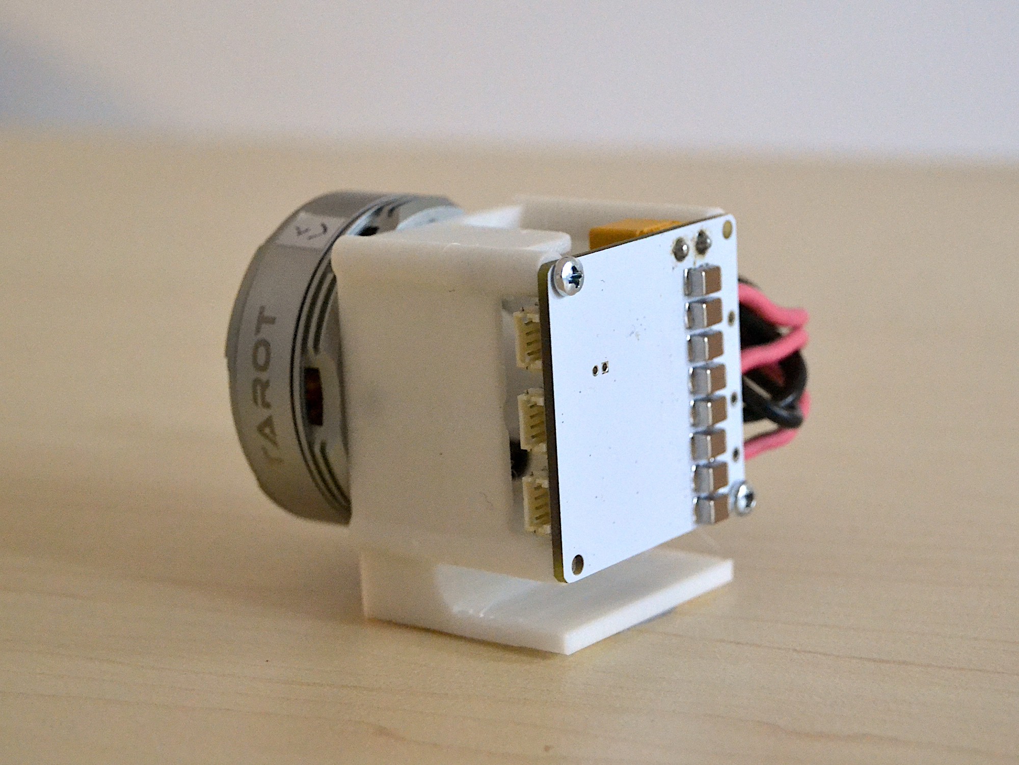
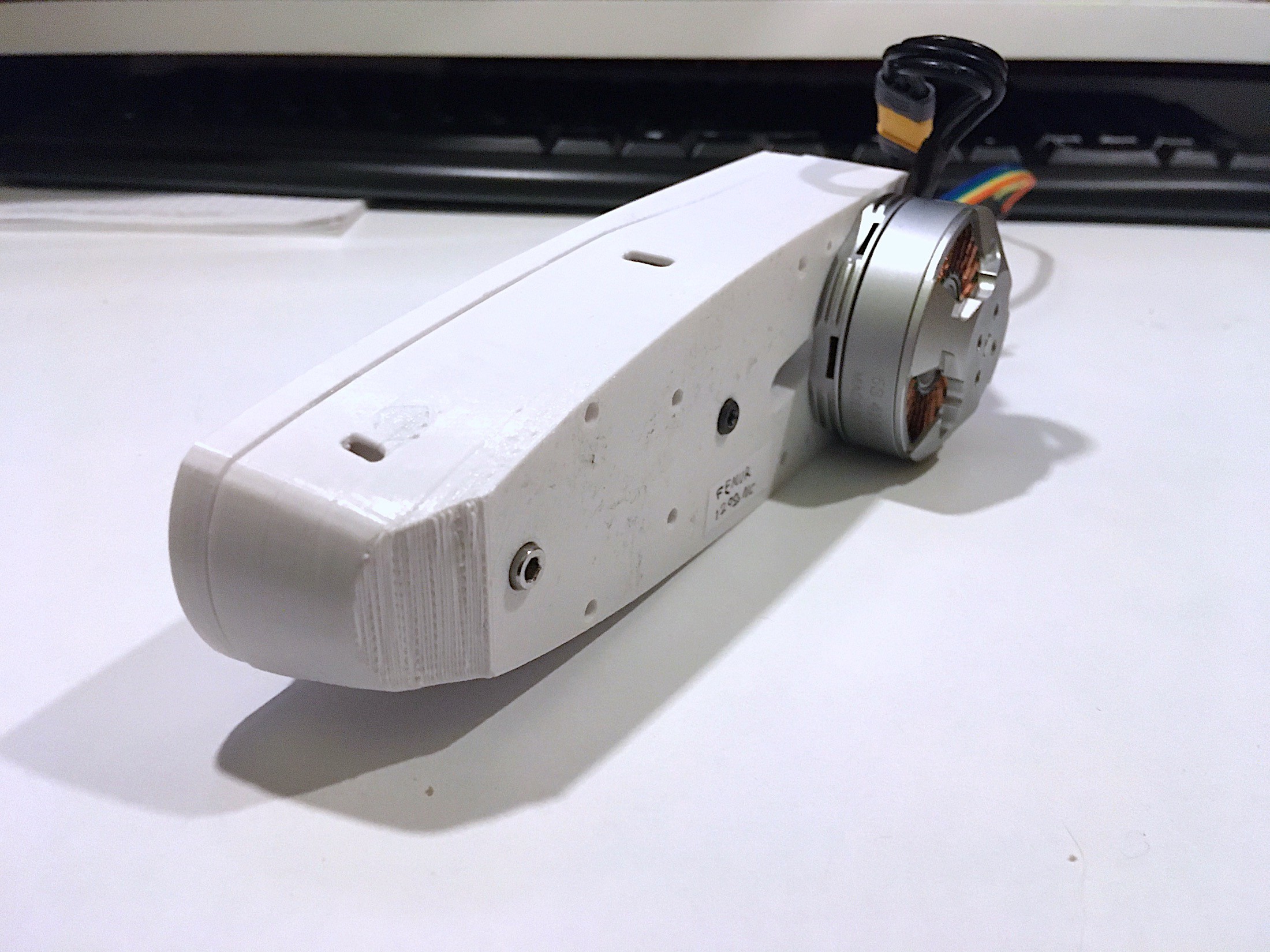
I've designed a new leg actuator for the quadruped robot that is more compact and completely encloses the electronics. Preview below:
![]()
Finally, I received note from the PCB manufacturer that the new R3 boards are on their way. I do expect a delay given the circumstances, but let's hope for the best :)
-
R3 in production, First Tinymovr integration to robotic leg
03/23/2020 at 19:07 • 0 commentsLet me start this log by wishing everyone good health in these extraordinary times. The COVID-19 pandemic has imposed strict rules that we are mostly unaccustomed to, however it is crucial that we remain patient and not deviate from our individual responsibilities in preventing further spread of the virus.
With most regions in China already recovering from the health crisis, PCB manufacturers are now able to undertake orders with a predictable time schedule, albeit inevitably with some delay. Having this in mind, I am happy to inform that I have sent the latest Tinymovr design, R3, to the PCB manufacturer as of yesterday. The boards are expected end of April/early May.
The R3 has several changes from the previous revision, featuring a Qorvo PAC5527 MCU, a MPS MA702 magnetic angle sensor, high quality TDK ceramic caps, compact DF13 connectors all over and holes for mounting XT30UPB power connector. Also, the pads for the motor leads are wider than in the previous release.
In addition to the above, I'm happy to report that the two remaining Tinymovr R2.1 boards in my possession are now integrated in the robotic leg that I mentioned in the previous log. Apart from some rotor synchronization issues arising from encoder limitations (outlined in previous posts), the leg seems to have no issue lifting 670g, with a maximum armature current of 8A:
Stay tuned for the next update!
-
R3 Production Schedule, CAN Bus Improvements, Robotics Demo
02/23/2020 at 21:29 • 0 commentsThe ongoing health crisis in China has affected PCB production and induced significant delays in PCB manufacturing and assembly. PCBWay, the manufacturer of Tinymovr prototypes, has announed delays of up to 30 days for small batch prototype runs. This is in addition to potential delays in shipping that are likely to be encountered.
Even though design of Tinymovr R3 is complete and has been carefully reviewed, I've decided to postpone sending the board to be manufactured until things settle down a bit and regular schedule is restored. This should incur a delay of about a month or so, which, in addition to a month between submitting design to receiving prototypes, should place the next round of Tinymovr boards in my hands late April 2020.
Taking advantage of this intermission, I've been working on a few improvements on the comms-side of Tinymovr, implementing a better CAN-Bus protocol that allows dynamic endpoint maps much like ODrive does. This goes in hand with an application I've been developing for interfacing and configuring Tinymovr from a PC/Mac, Tinymovr Studio.
As soon as I achieve some progress in this, I'm planning a robotics demo as a follow up to demonstrate application of Tinymovr. The demo will feature a 2DOF robot leg that uses Tinymovr R2 in both DOFs, with daisy-chained power and comms.
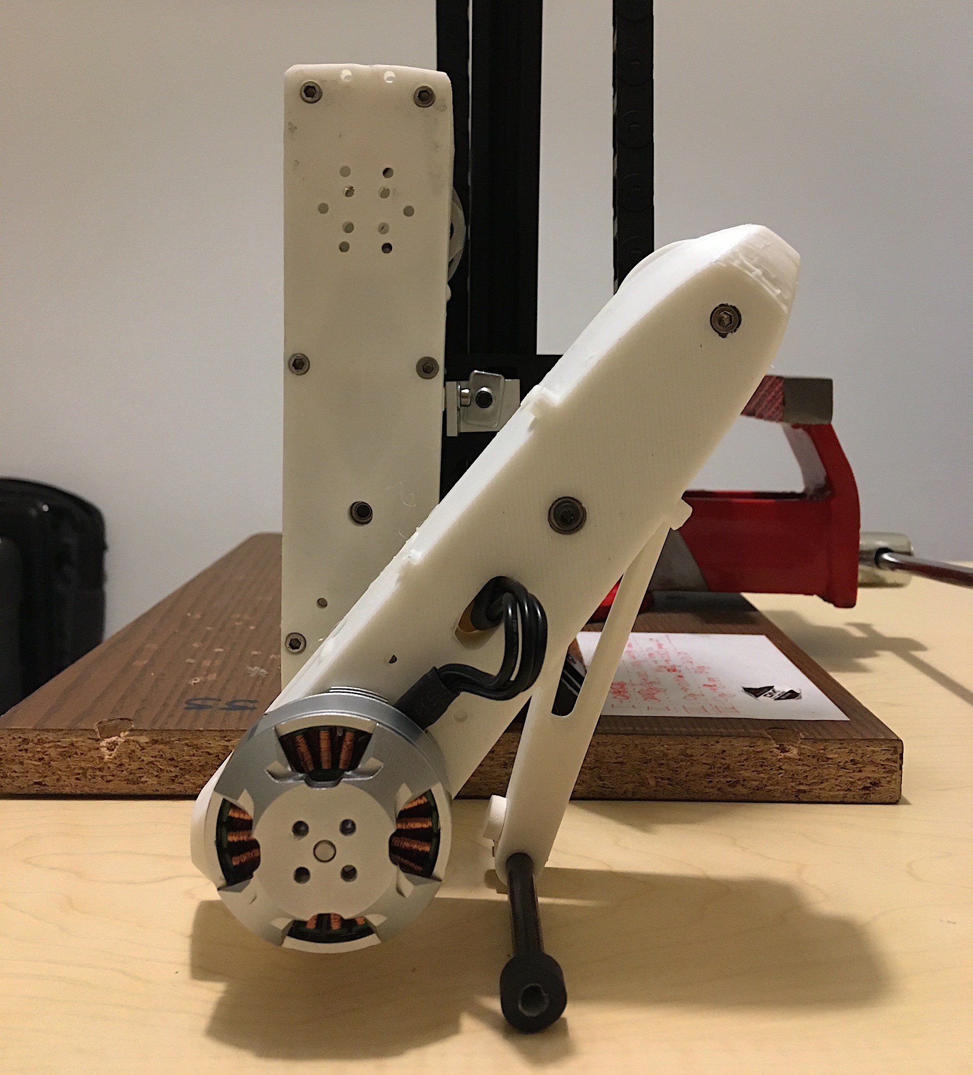
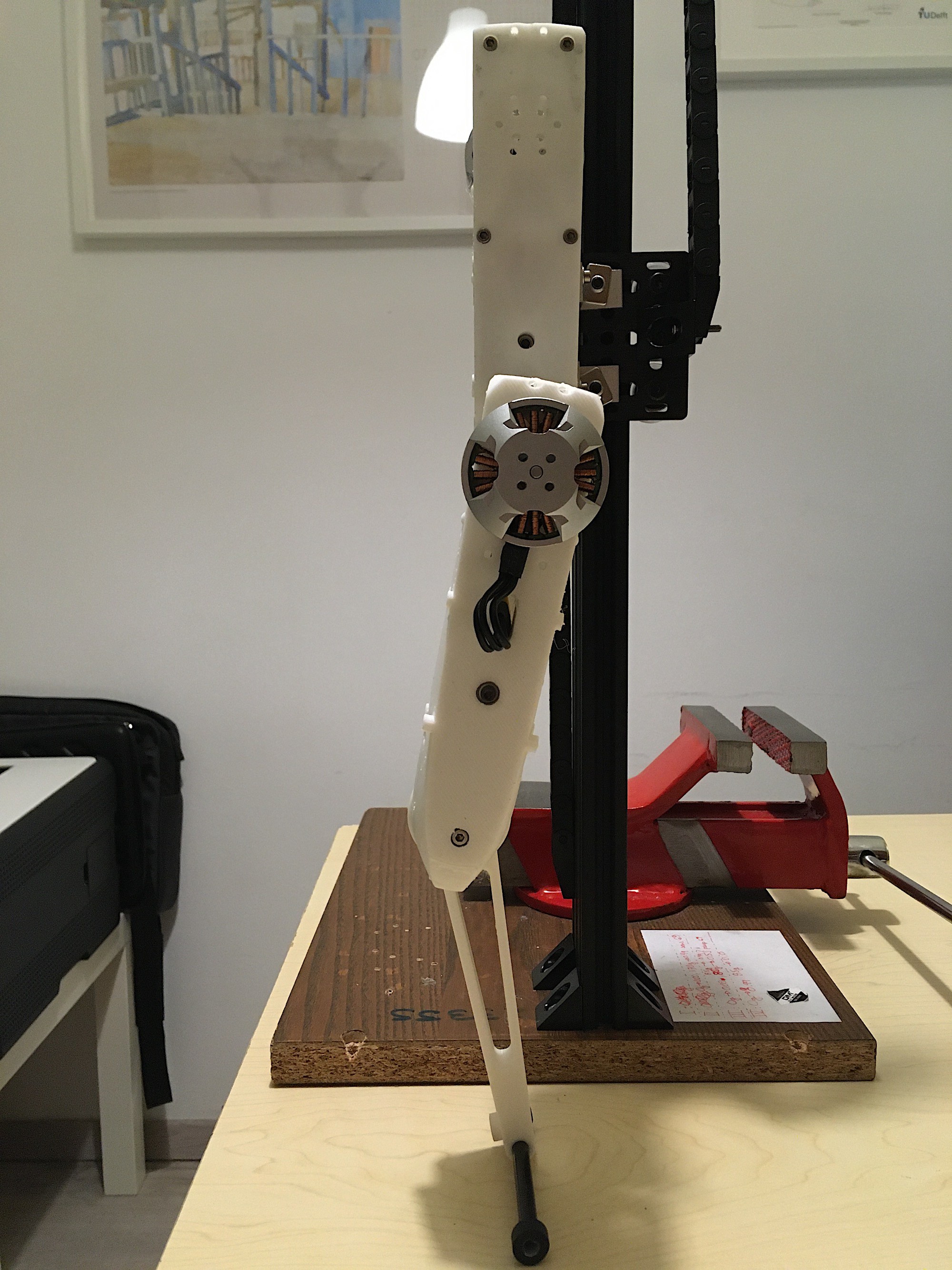
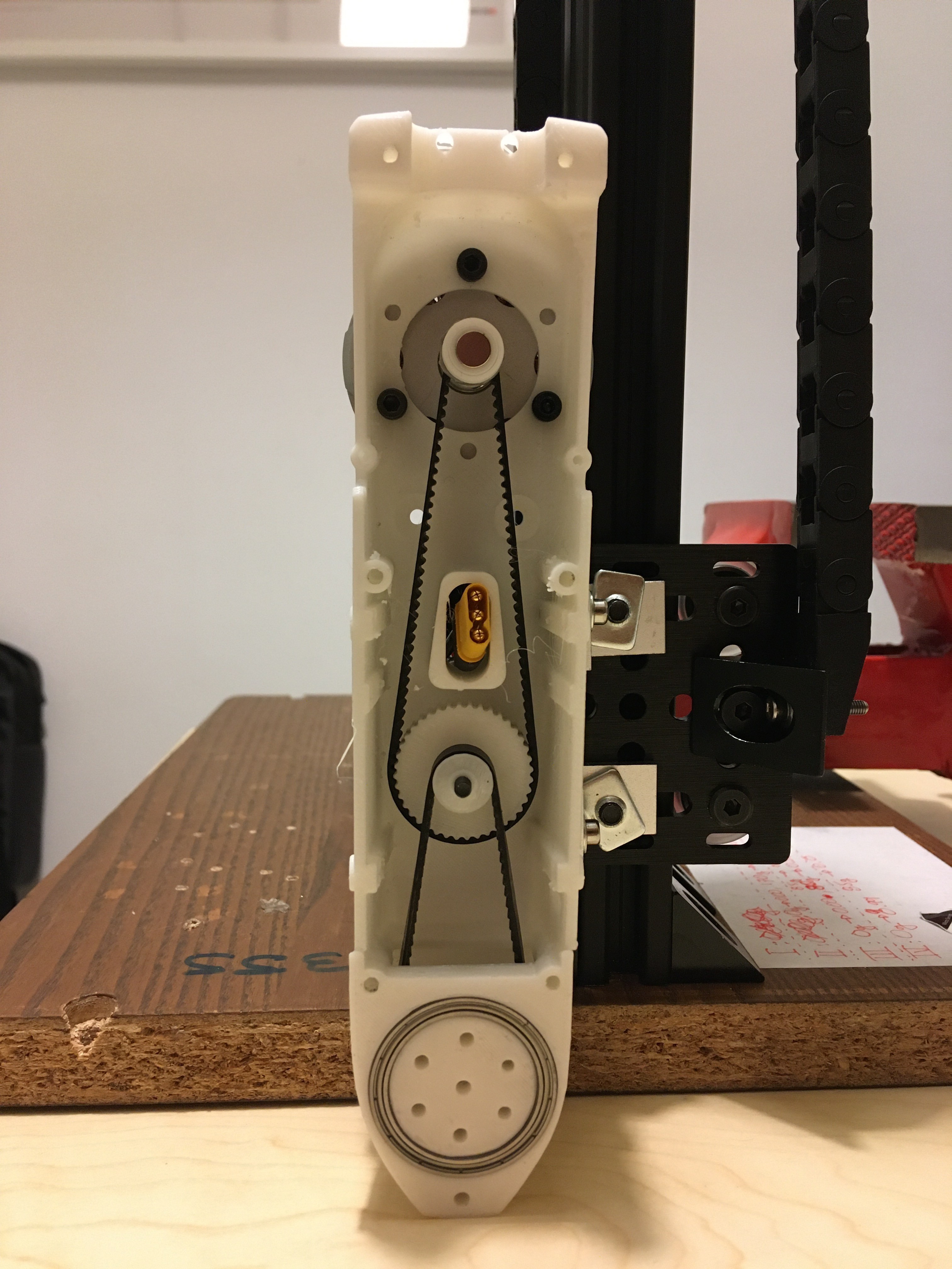
Here's a preview of the mechanical assembly, which is almost ready:
![]()
![]()
![]()
This is a dual-belt-in-series arrangement that is heavily influenced by the Solo quadruped robot of the Open Dynamic Robot Initiative. The belt transmission achieves a 1:10 reduction in a compact package that fits well to the elongated form of the leg itself. The plan is to have Tinymovr R3 integrated in the leg assembly, right opposite the motor, where the encoder magnet is found. The first order of things is to get some simple kinematics working, and following that maybe try to implement some dynamic movements such as jumping.
Stay tuned for more updates!
-
R2.1 Testing and Next Revision
01/28/2020 at 16:43 • 0 commentsI've just finished testing a bunch of Tinymovr R2.1 boards, and results look promising, save for a few issues I have discovered along the way.
The following functional aspects are fully tested and working in this latest revision:
- 3-phase PWM MOSFET driving at 20kHz
- Current sensing ADC for all three phases
- MA730 absolute encoder readings over SPI at 1MHz, encoder observer with velocity output
- Motor control loop at 10kHz (position, velocity, current control, position limiting, current limiting, velocity-dependent current limiting)
- Calibration of resistance, inductance and absolute encoder offset
- Overcurrent protection, undervoltage protection
- UART communication with simple protocol for configuration
- CAN Bus communication with comprehensive protocol and error handling. Bidirectional messaging tested up to 1kHz, @ 500kHz CAN bus speed.
- Basic configuration saving and loading to/from NVRam
In the following video, CAN bus at 500kHz is used for bidirectional communication. Initially, the arduino issues a calibration command and checks if successful. Then, it sends a series of position commands at random intervals, and also requests position and velocity information at a rate of 500Hz, which is then retransmitted via Arduino serial and plotted using Serialplotter.
I’m planning a demo of a fully integrated (motor+controller) 2DoF robot leg, which will use 2x daisy-chained Tinymovr boards. More on that in future updates.
During my testing I’ve encountered a series of issues, briefly outlined below:
The first issue is with the encoder. This document by MPS describes an aspect of the MagAlpha encoder series that I have overlooked. In a nutshell, MagAlpha series encoders include a digital filter that introduces a tradeoff between encoder resolution and bandwidth. The MA730 used in Tinymovr has a high time-constant filter that allows for a 14-bit resolution but limits the bandwidth to 23Hz, according to the above document. In high acceleration scenarios, this makes the reported position lag behind significantly. Since the electrical angle is computed from the encoder, this also affects motor efficiency, and in some cases even throws the control loop out of whack.
In the video above, you may notice some oscillations around the velocity setpoint, which are more profound in higher velocities. I have pinpointed this to be caused by the combination of motor cogging torque and encoder filter time-constant.
To mitigate such issues in the next revision, I’ll be using a lower 12-bit encoder, the MA702, which however has shorter time-constant filter that allows a reported 400Hz bandwidth. This should be sufficient for all but the most demanding acceleration scenarios.
Another issue is with the power stage. It seems I miscalculated the values of the resistors that control slew rate and the board suffers from significant ringing during switching. Ringing is clearly visible in the oscilloscope, especially during switching at zero torque.
Even though it would be straightforward to just replace the resistors, I’ve decided a more radical change for the next revision that will hopefully bring more benefits. Qorvo recently released PAC5527, an MCU that is much like the PAC5523, however it has many of the external components found at the power stage embedded in the die. PAC5527 has a software adjustable slew rate and can work with input voltages of up to 48V.
Replacing the PAC5523 with the PAC5527 would bring several benefits to Tinymovr, the most important of which are:
- Higher rated input voltage range (48V up from the current 20V)
- Easier configuration of power stage parameters
- Reduced component count, which translates to more flexible board layout.
The higher rated voltage will also warrant changes to several passives, but also to the FETs which are currently rated for 30V.
While the above seem to require fundamental design changes, the fact is that all replacement parts are pin-compatible with existing ones, save for the inverter pins of the PAC5527. This means that the only part of the board to be redesigned will involve the gate driver traces, however this will be much simpler compared to the current power stage which includes much more passives as well as actives.
I’ll be updating this blog with progress on the next board revision, so stay tuned!
-
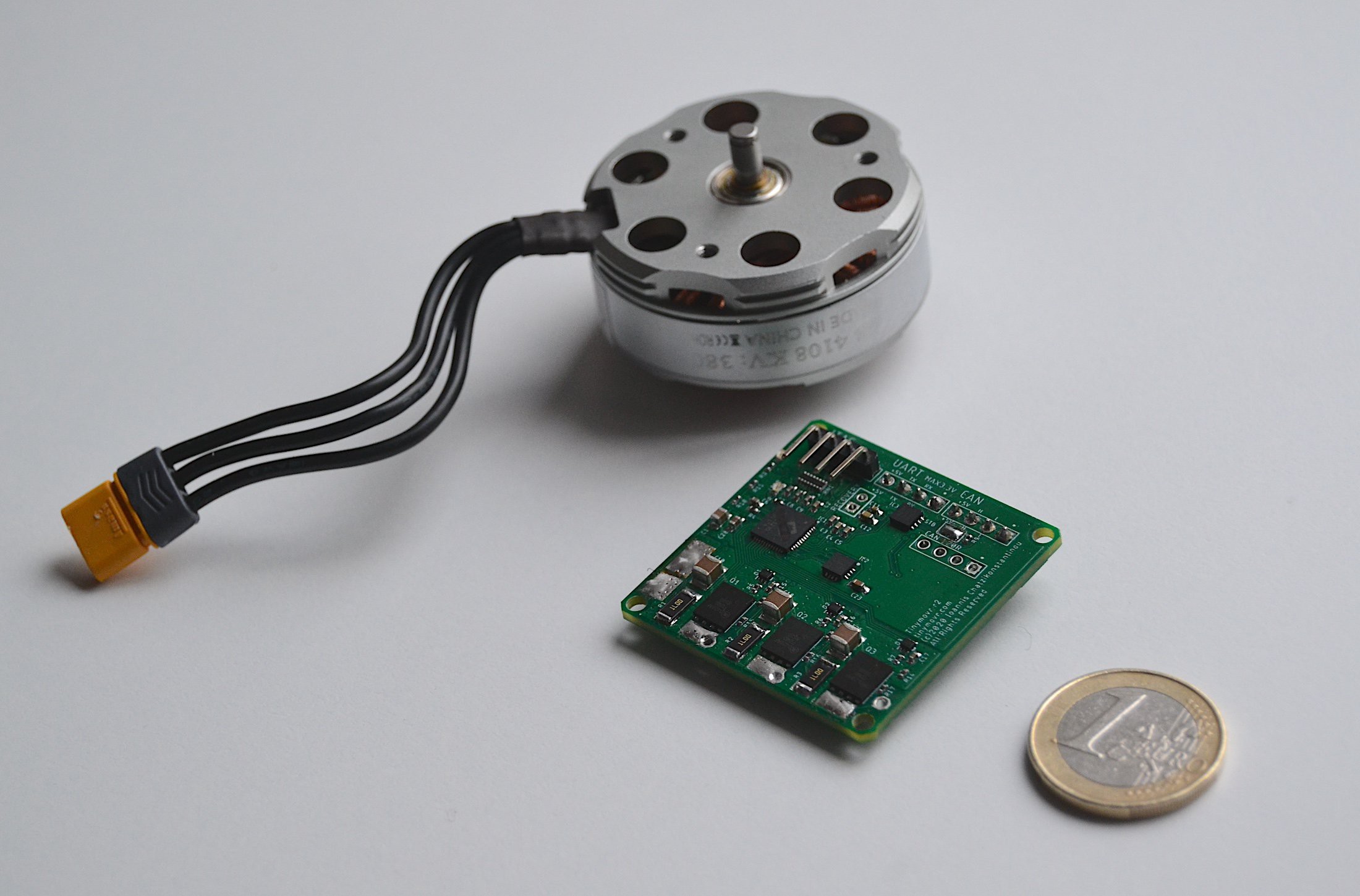
R2 arrives, size comparison
01/18/2020 at 15:42 • 0 commentsTinymovr r2 PCBs have recently arrived from China. In the meantime I've been improving the firmware, and at the present motor control (position, velocity and current) as well as CAN Bus and UART connectivity are fully functional.
![]()
Below is Tinymovr R2 next to a one Euro coin and a 4108 motor for size comparison.
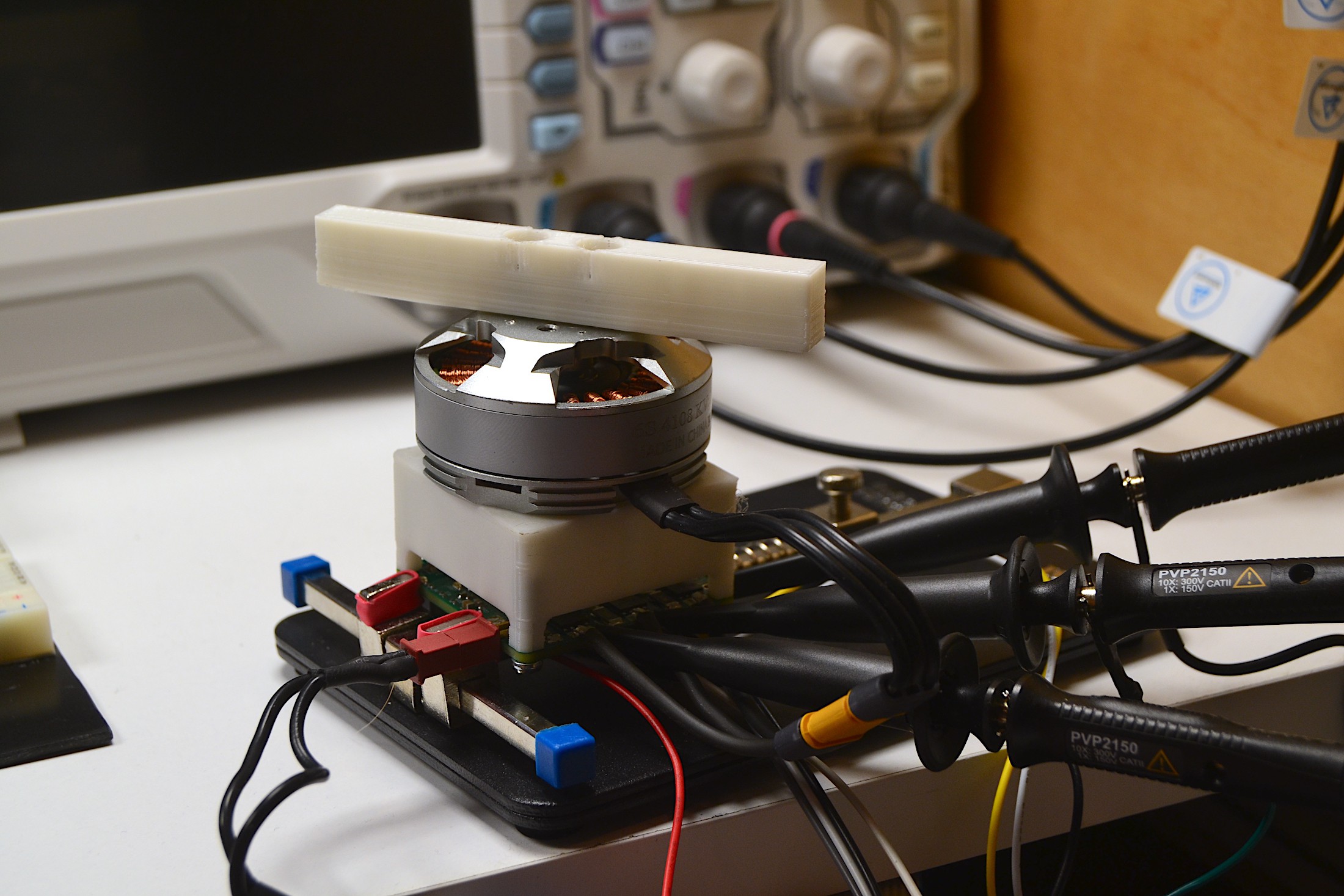
![]()
New motor testing bed with UART, CAN Bus connections and oscilloscope probes.
![]()
As mentioned previously, this board revision replaces the AS5047 encoder for the MA730, which comes at a significantly lower cost. In addition, the power stage includes larger shunt resistors and 2oz copper traces, allowing a max calculated current of 30A continuous (with proper mosfet cooling).
Stay tuned for more videos of the board in action!
-
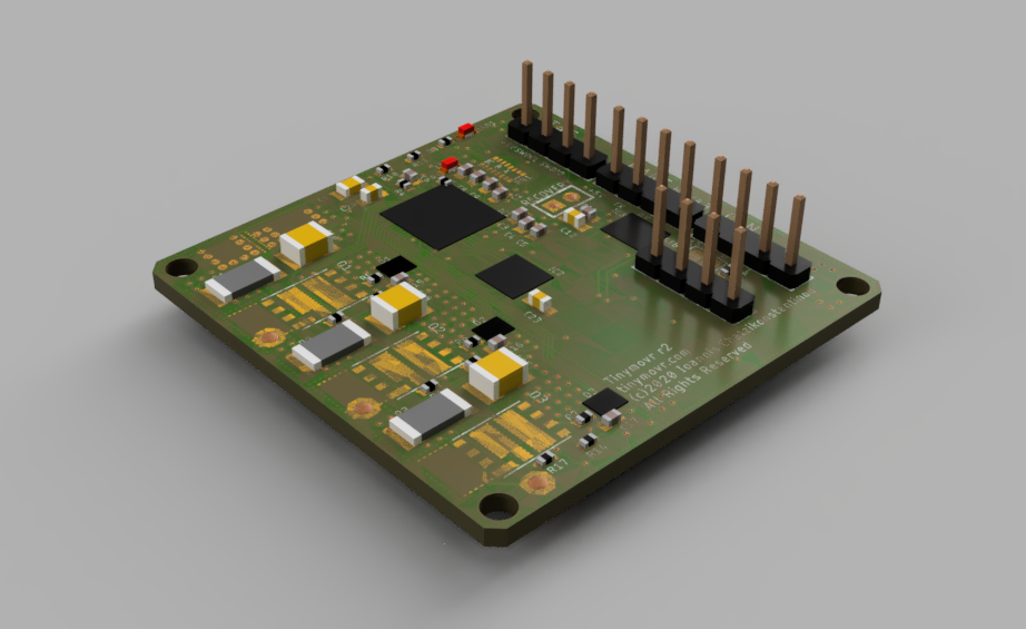
Tinymovr r2 design complete
12/15/2019 at 10:14 • 0 commentsThe design of Tinymovr r2 is complete. The board measures 40x40mm, that is 4mm less than r1 on each side. It also features a new magnetic angle sensor, MA730 by Monolithic Power Systems (MPS), which is lower cost than the AM5047/AM5048, and therefore further pushes down the cost of the driver.
The new board also features beefier shunt resistors which allows it to handle bigger currents.
Here below is a preview rendered using Fusion360. Not all components 3D models are available, so some are not visualized.
![]()
Boards will be arriving early January, and I'll be reporting on initial testing shortly after.
-
CAN Bus Testing
12/02/2019 at 22:08 • 0 commentsI've just completed the first implementation of CAN Bus for Tinymovr. A basic set of instructions is implemented so far, but more to follow.
In the tests below Tinymovr achieved a command rate of 500Hz for velocity and position commands, which is satisfactory for high-resolution control.
Tinymovr Motor Controller
Affordable, precise, integrated motion control for robotics