 Eric
EricThis blog is being transferred from my own website to Hackaday so this post is going to serve as a summary of progress from inception to present-day.
Earliest post
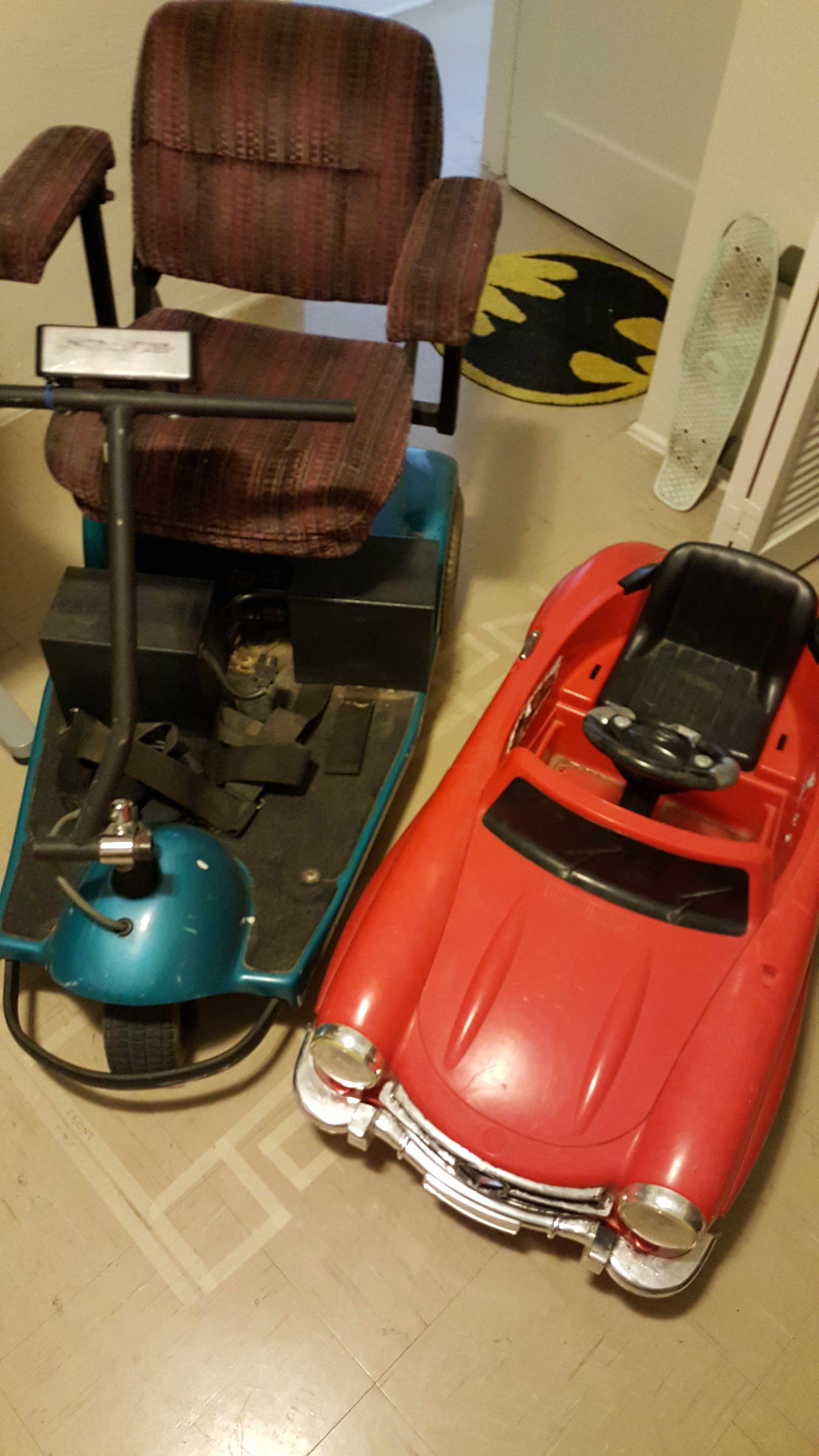
Since I'm starting from scratch and I don't know anything about go-karts, I decided to start out by putting together a BOM of obvious components and start tweaking in the direction of what seems like success. I found a really nice sale on some slick wheels at BMI Karts (along with a bunch of few other things). I was also having a lot of trouble finding a Power Wheel and a cheap mobility scooter to salvage parts from and, as soon as I put out a notice on Facebook, I found a good pair of deals on Craigslist for exactly a Mercedes Benz 300SL Power Wheels and mobility scooter. High quality German engineering.

After what seemed like forever building up a bill of materials, I finally ordered the first batch of parts. I would have spent longer designing and measuring stuff out in CAD, but BMI Karts was having a pretty irresistible sale on some stuff I would eventually need and sometimes you just need to have the parts in your hands to get a better understanding of how everything should go together. I got a set of wheels, a steering column, steering spindles and brackets, a pair of tie rods, a steering wheel, and a pair of pedals. After receiving the parts, the steering wheel is probably too big and the pedals too heavy but I paid $4 total for both of them so I’m not crushed.
Instead of pulling apart the car right away, I decided to piece out the scooter so I could figure out what parts I’ll be able to use. All the scooter yielded was a transaxle and a pair of two-piece rims, but that's all I was really hoping to get out of it. The wheels I bought online are all free wheels so the plan is to pull the tires off of two of them and put them on the scooter rims. Luckily, the tires happened to be the exact same size that the scooter used which was pure serendipity and something I did not plan for. Very neat.
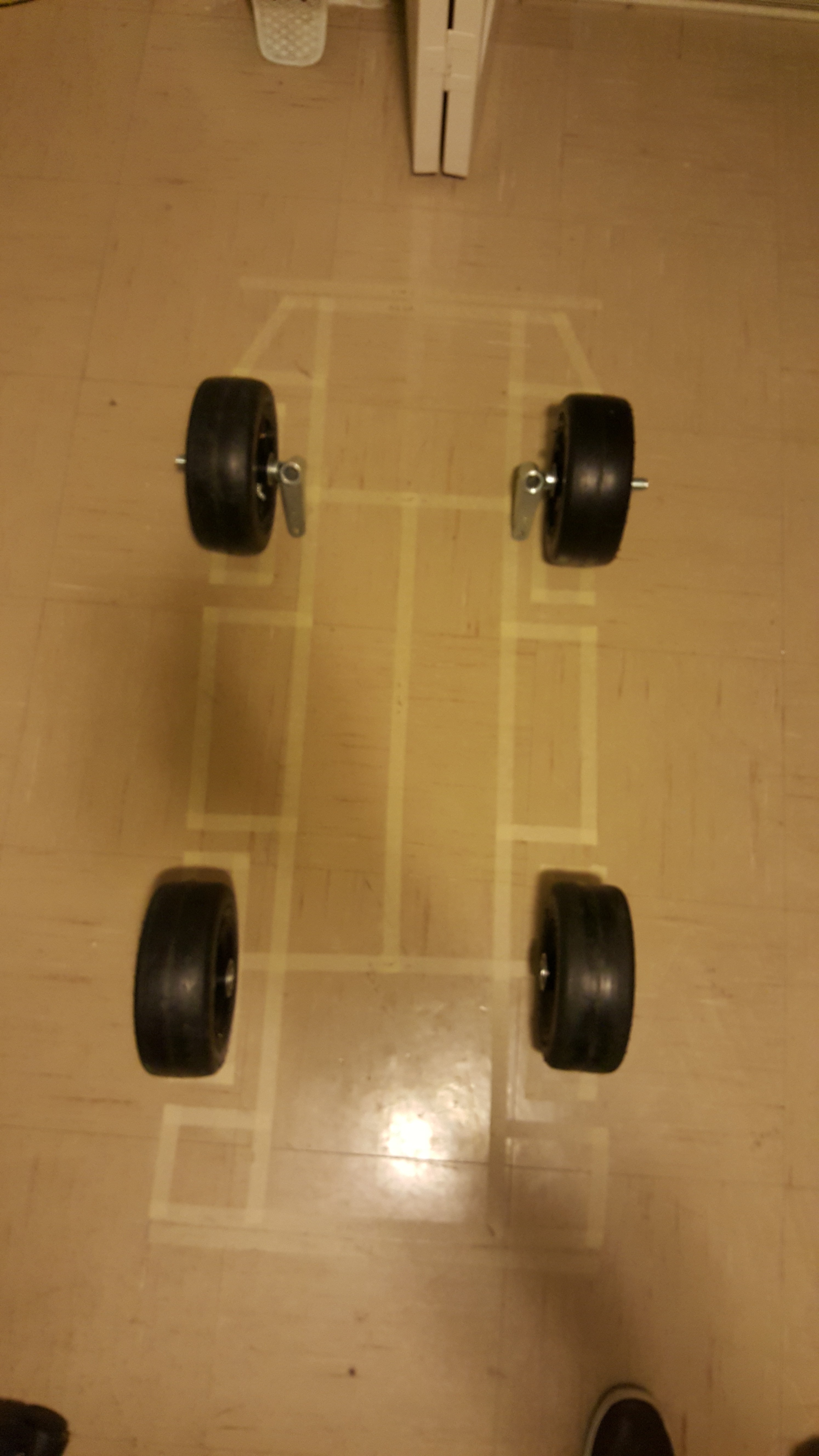
The Power Wheels I bought was way too small for a full grown man-child as myself to fit into, so I had to do a bit of modification. I put down a tape outline of the planned wheelbase of the car on my floor and sat in it to get an idea of how big everything would need to be. The dimensions I had come up with seemed to be just big enough to fit me but the Power Wheels was much too small to wrap around the potential frame.
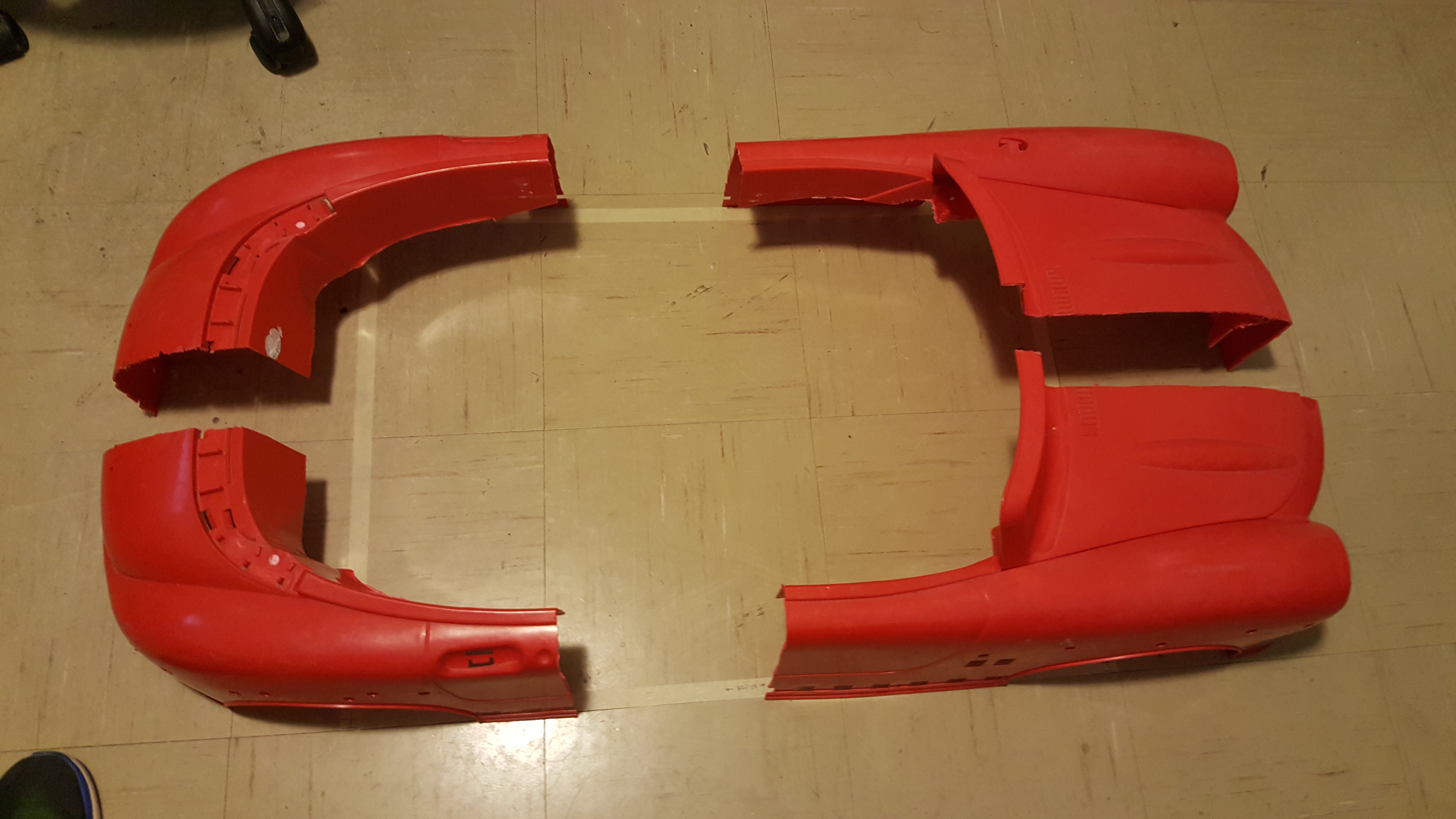
I initially cut out the base of the body to see if I could fit inside without the seat and floor to no avail so it turned into a full on quartering. I stitched the thing back together with some good old cardboard and duck tape so its width fits nicely around the salvaged transaxle and the rest of the shell lined up with the lines taped on the floor. The next step with the “biggening” of the body was to get some bondo or modeling clay and fill out the holes so it's smooth and streamlined again.
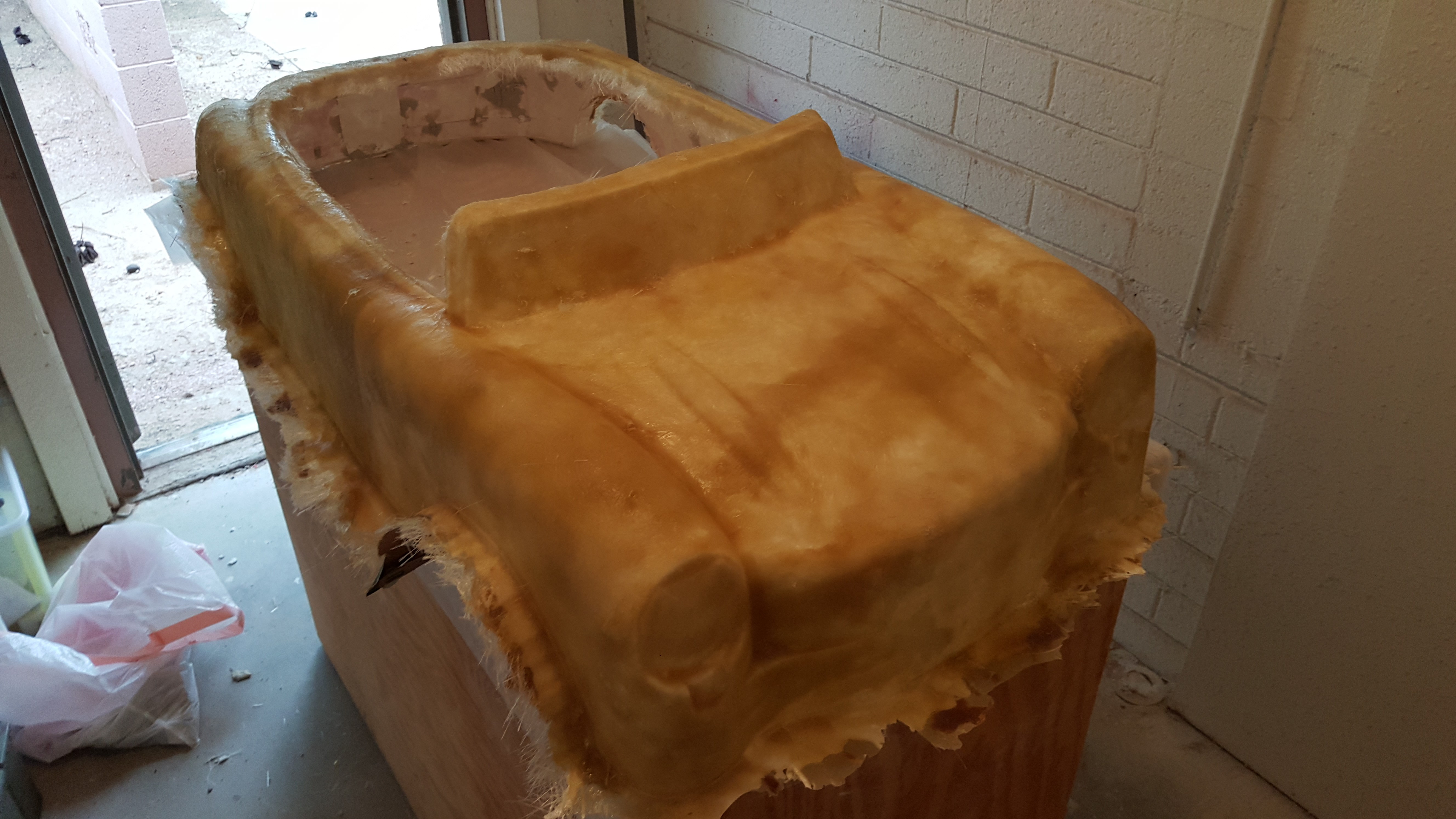
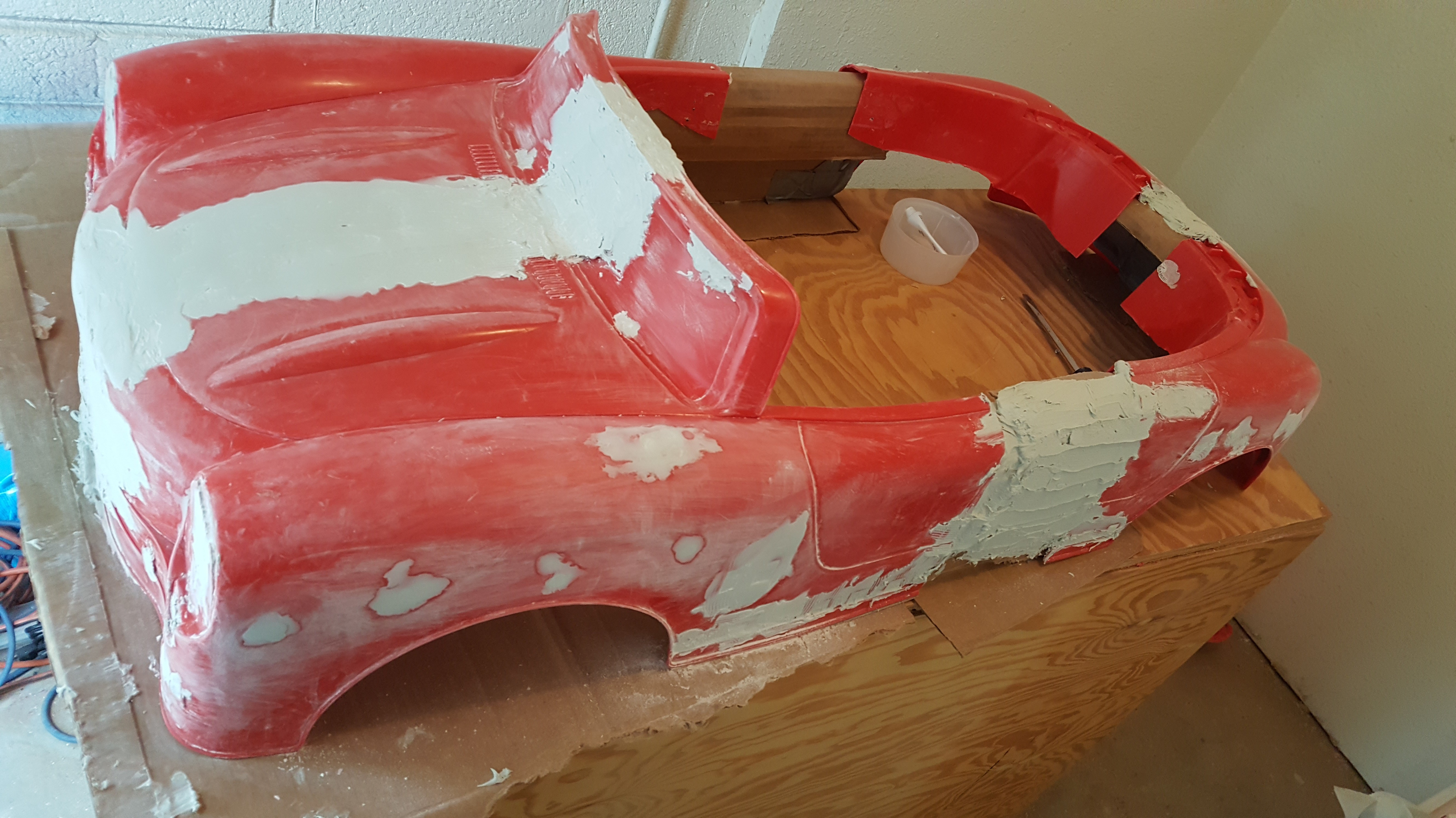
Making everything nice and pretty took much longer than I had hoped. I severely underestimated the amount of putty-ing and sanding and re-putty-ing and re-sanding that’s required so the process went on for quite a while. The detailing power sander had become pretty much my best friend along with second best friend belt sander. It’s super satisfying to just hold a power tool against a rough patch of Bondo and watch it turn super smooth.
It took forever, but I finally got a smooth body over which to apply a fiberglass shell. Creating the buck for the fiberglass was time consuming, but fiberglassing is probably one of the worst things ever. The resin is sticky, dissolves everything, and just ruins everything it touches. Fiberglass frays everywhere and sticks to everything via splashed resin. It took several grueling hours of brushing and tapping resin into every dry crack of fiberglass but I finally finished and will never do that again unless it's absolutely the only answer.
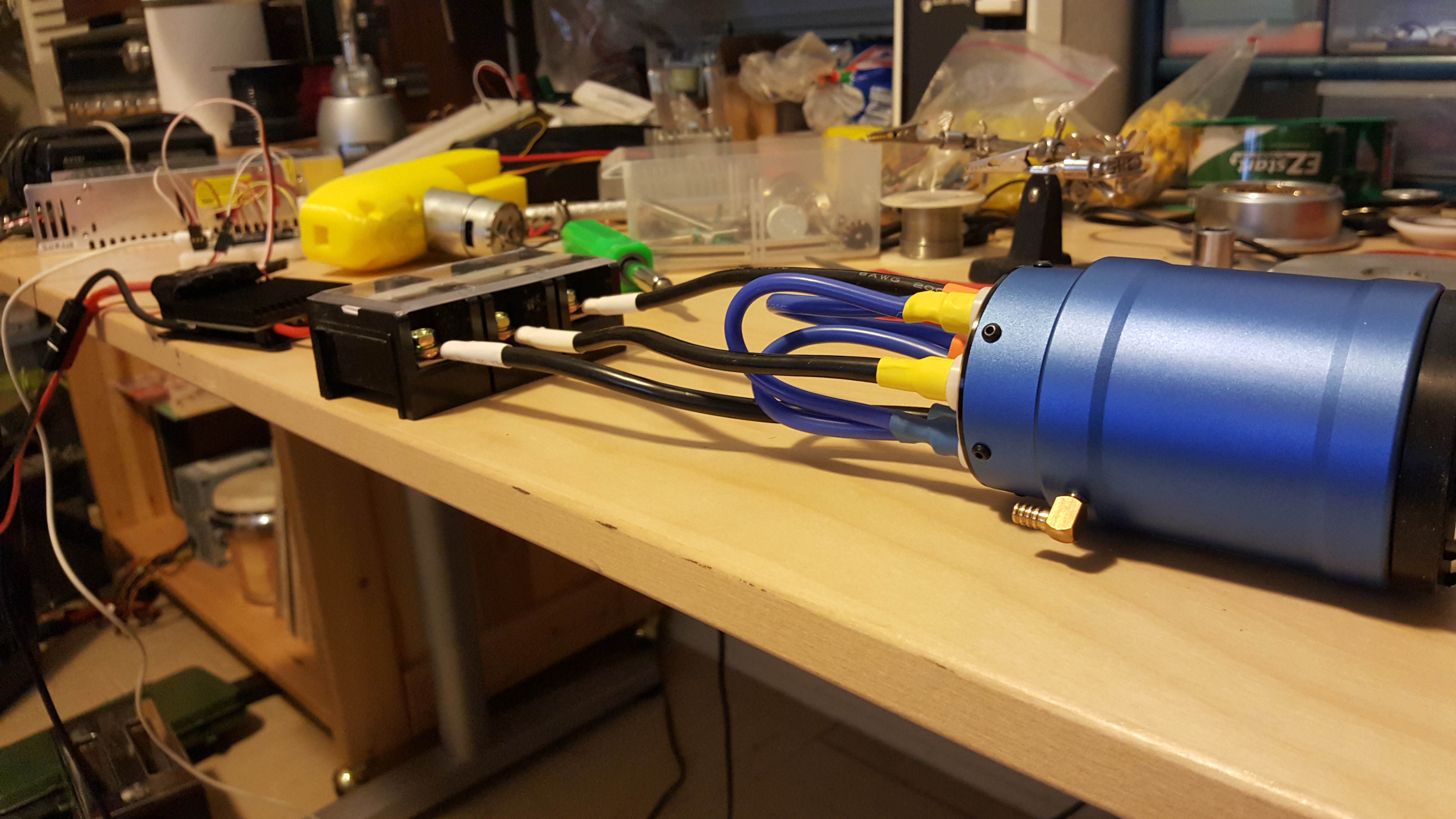
I ordered some of the major electronic components online a while ago and finally got to testing them. I bought a 6.5A 36V power supply off eBay to test all the electronics, a Turnigy Sentilon 100A ESC and a Turnigy Aquastar T20 brushless DC motor from HobbyKing, and an Arduino Micro and various connectors and hardware from Amazon. I put together a quick test to see how the ESC worked with the Arduino using all aforementioned components and an RC controller. There was some disagreement at the high and low end of the Arduino’s PWM output but overall, it worked.
Initially I had planned to use just bare PIC microcontrollers throughout the car but ended up going with Arduino micros. Although I would probably learn more with PICs, Arduino is just too easy and requires so little work for setup for me to dismiss it. Also I just wanted to get everything finished, so the quickest and easiest option is the best option in this case.
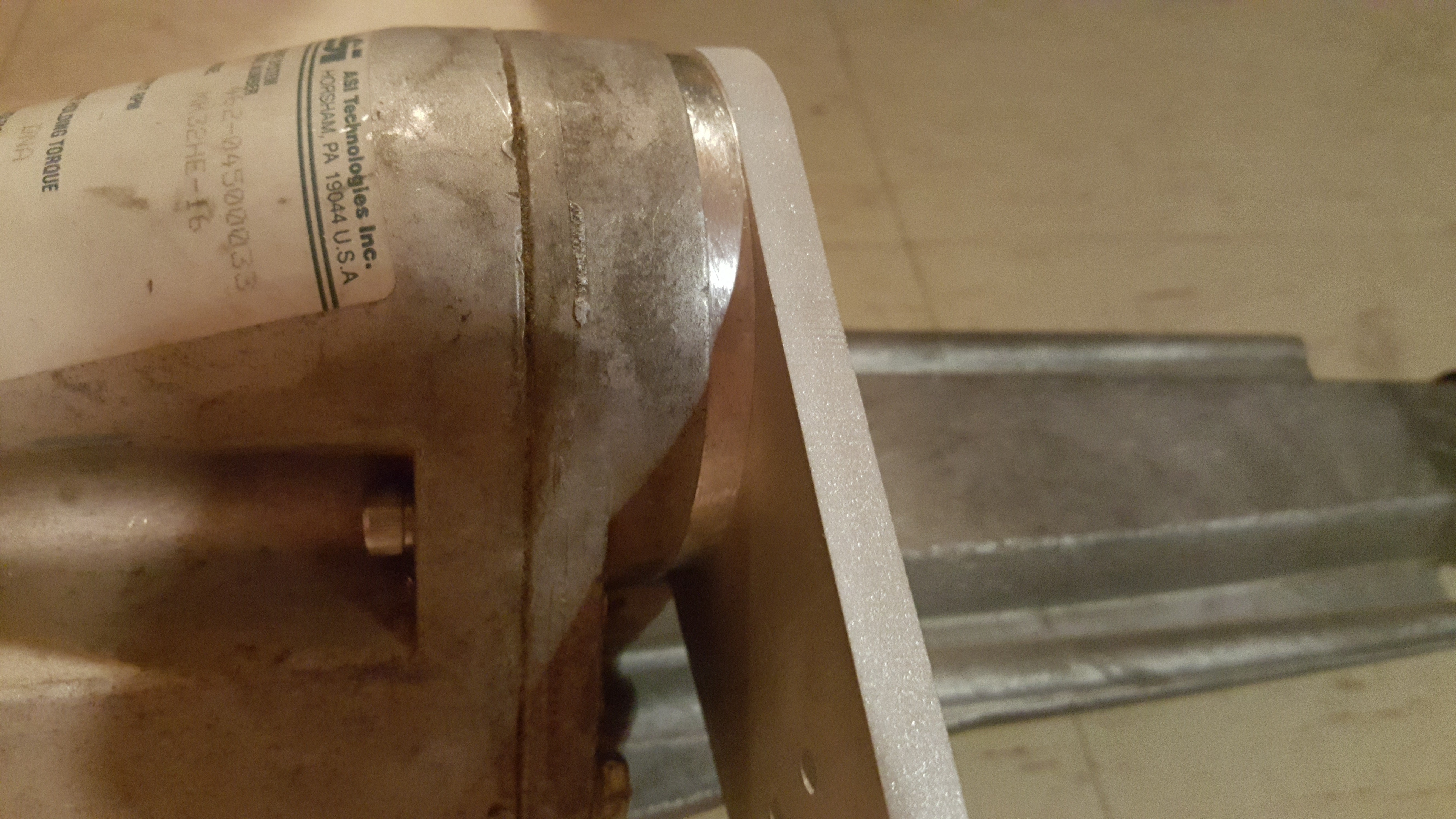
I had some pieces water-jet-cut out of 5/8″ aluminum for spacing and support of the motor in the transaxle. Lucky for me, my dad has some very skilled connections that are willing to help out in exchange for beer and hockey.
There’s a 9-tooth sprocket for #25 chain held in place on the motor's D-shaft by some 3D printed spacers and a lock nut. The lock nut stays there because I threaded the hardened steel shaft just enough to keep the nut there. That was another process that took a very long time, mostly because I don’t think you’re supposed to be able to thread hardened steel shafts.
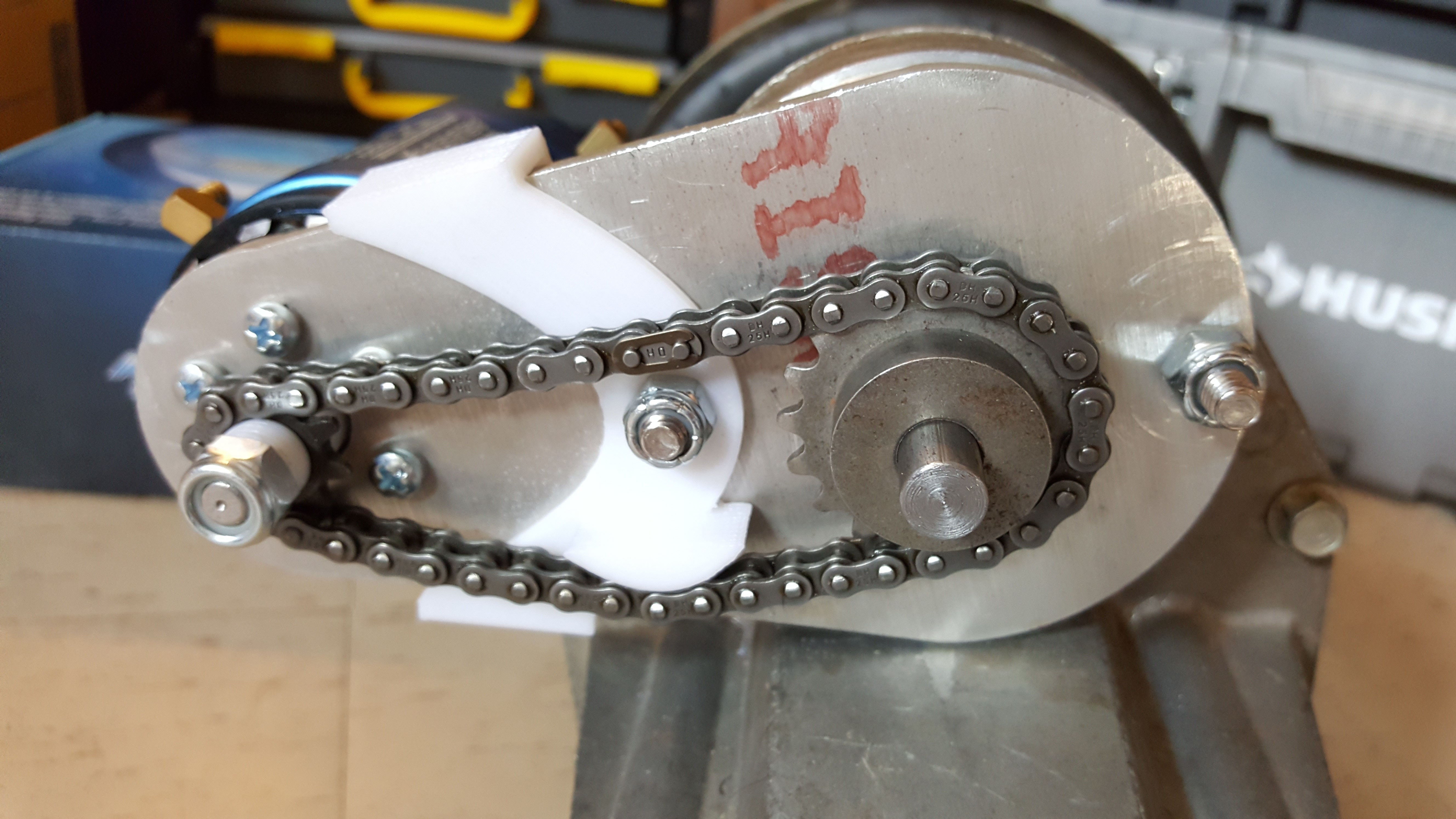
I planned on just welding the sprocket to the driveshaft because I didn’t have the resources to cut keyways. The driveshaft has a little groove for a retaining ring to keep it between the motor mounting plate and snugly inserted in the transaxle, I’m pretty happy with how well it all fits together. I designed the shaft to pretty much replace the scooter motor shaft and I happened to know someone who was able to machine it by hand perfectly, which was very fortunate for me. The chain is super loose on the sprockets so I 3D printed a tensioner that I’m hoping will stand up to the wear. If it doesn’t work out, it was super cheap to make anyways and I can always design a better tensioner or tensioning sprocket.
I came up with a super simple frame that is designed around the U-shaped bracket that came with the transaxle. I made the jig out of wood that was stored in the rafters of the house my parents recently bought because free wood. Before I ended up renting a chop saw to cut the square tube I tried using an angle grinder with a cutting wheel, but that didn’t work out as all my cuts were jagged. Lesson learned. The next step was to do some welding, which I had to outsource because it’s impossible to rent MIG welders for some reason (I recently found out it’s because renting out the gas would be a liability).
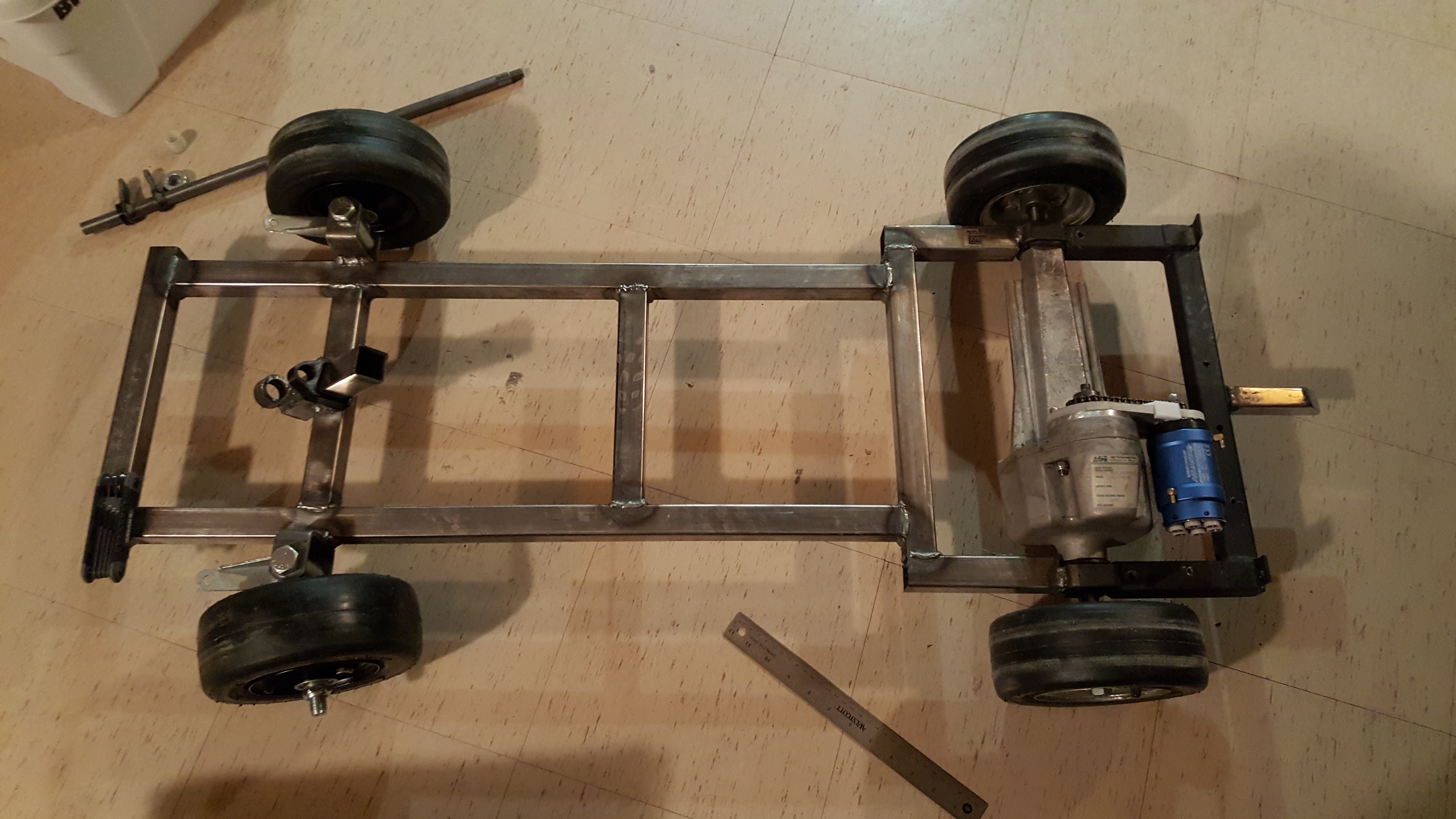
Most recent post
So I got a nice guy at a makerspace to do the welding for me because it’s impossible to get access to MIG welders where I was living at the time. The drive sprocket is now welded to the shaft and everything spins pretty smoothly. When I plugged the motor into my 36V bench power supply everything spun up real good.
I got the stuff that makes up the steering column nice and put together with a great 3D printed bracket that doesn’t shatter when I bump the column which is always a plus. The tie rods I originally got in the steering kit were too long by like six inches so I replaced them with some regular threaded rods cut to size.
Discussions
Become a Hackaday.io Member
Create an account to leave a comment. Already have an account? Log In.