 schwarzrmsu
Now that I have figured out digital outputs & delays, the next logical step would be to play with those new features while introducing digital inputs as well. A portion of the design that requires digital output controls, reading digital inputs and delays is the key pad. In order to understand the keypad software, I will give an explanation of the keypad hardware.
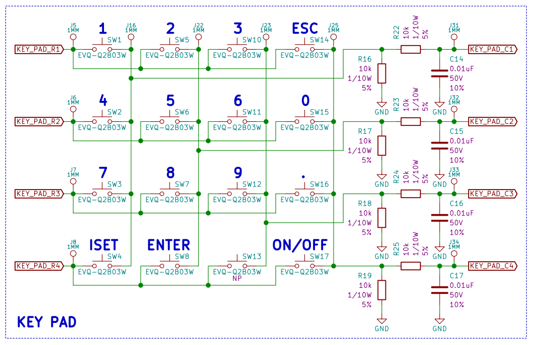
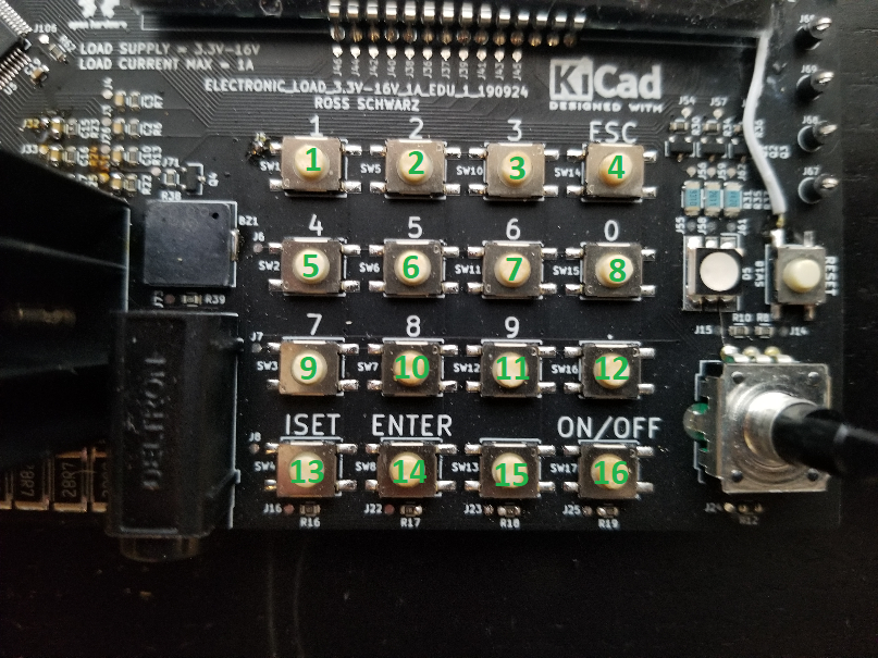
The key pad consists of 16 push buttons:
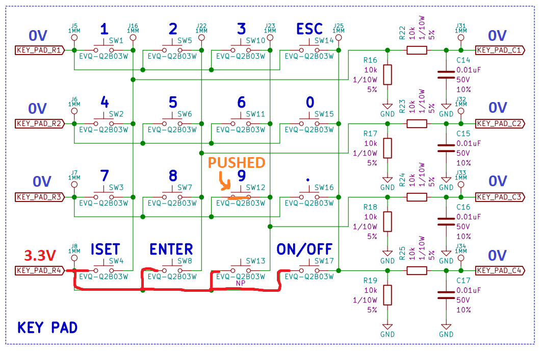
Schematic View:
PCBA View:
The simplest approach would be to tie all 16 push buttons to a voltage source (3.3V) and route the normally open end of each push button to a discrete digital input. The problem with this approach is it would require 16 GPIO pins on the micro which is a lot for one feature. In order to minimize the required number of GPIO, I used a multiplexed approach which only requires 8 GPIO.
The best way to explain the multiplexed approach is to go through an example. I will show you how the micro-controller will determine that the 9 key (push button 11) is being pushed.
The micro-controller is going to individually power each row, one at a time using digital outputs I named KEY_PAD_R1, KEY_PAD_R2, KEY_PAD_R3 & KEY_PAD_R4. While each row is getting powered individually, the micro-controller is going to check each column one at time using digital inputs I named KEY_PAD_C1, KEY_PAD_C2, KEY_PAD_C3 & KEY_PAD_C4.
When KEY_PAD_R1 digital output is high, this is what the micro-controller will see when the 9 key is pushed:
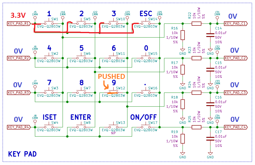
You can see all digital inputs are reading 0V which is an indication that the 1, 2, 3 or ESC keys are not being pushed.
When KEY_PAD_R2 digital output is high, this is what the micro-controller will see when the 9 key is pushed:
You can see all digital inputs are reading 0V which is an indication that the 4, 5, 6 or 0 keys are not being pushed.
When KEY_PAD_R3 digital output is high, this is what the micro-controller will see when the 9 key is pushed:
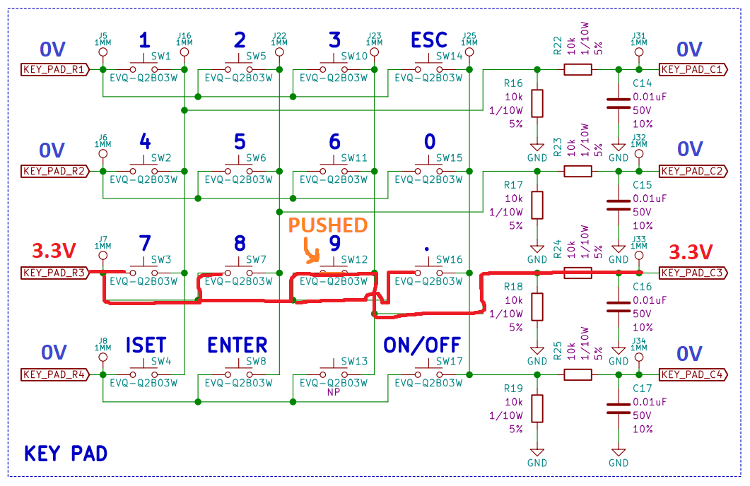
You can see in this scenario, the KEY_PAD_C3 digital input is reading 3.3V. The micro will have the 9 key mapped to this condition of KEY_PAD_R3 digital output high & KEY_PAD_C3 digital input high. In fact all keys will have a unique combination that will allow to the micro-controller discretely identify when each key is being pressed.
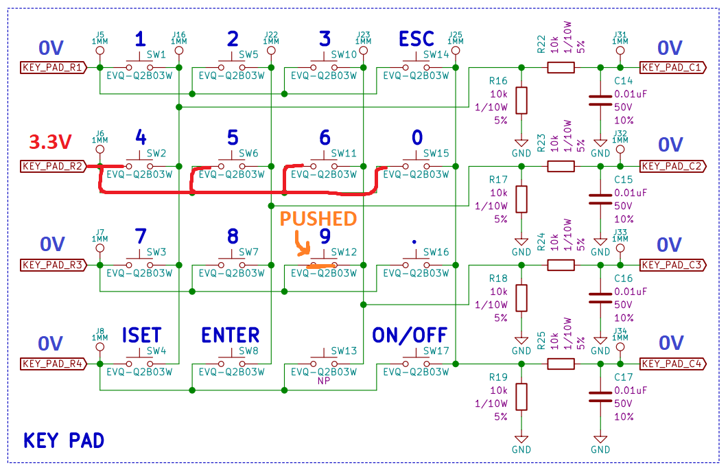
Lastly when KEY_PAD_R4 digital output is high, this is what the micro-controller will see when the 9 key is pushed:
You can see all digital inputs are reading 0V which is an indication that the ISET, ENTER, NULL or ON/OFF keys are not being pushed.
The logic in the micro-controller can be mapped to this table:
KEY_PAD_R1 Digital Ouput High & KEY_PAD_C1 Digital Input High = 1 Key is pressed
KEY_PAD_R1 Digital Ouput High & KEY_PAD_C2 Digital Input High = 2 Key is pressed
KEY_PAD_R1 Digital Ouput High & KEY_PAD_C3 Digital Input High = 3 Key is pressed
KEY_PAD_R1 Digital Ouput High & KEY_PAD_C4 Digital Input High = ESC Key is pressed
KEY_PAD_R2 Digital Ouput High & KEY_PAD_C1 Digital Input High = 4 Key is pressed
KEY_PAD_R2 Digital Ouput High & KEY_PAD_C2 Digital Input High = 5 Key is pressed
KEY_PAD_R2 Digital Ouput High & KEY_PAD_C3 Digital Input High = 6 Key is pressed
KEY_PAD_R2 Digital Ouput High & KEY_PAD_C4 Digital Input High = 0 Key is pressed
KEY_PAD_R3 Digital Ouput High & KEY_PAD_C1 Digital Input High = 7 Key is pressed
KEY_PAD_R3 Digital Ouput High & KEY_PAD_C2 Digital Input High = 8 Key is pressed
KEY_PAD_R3 Digital Ouput High & KEY_PAD_C3 Digital Input High = 9 Key is pressed
KEY_PAD_R3 Digital Ouput High & KEY_PAD_C4 Digital Input High = . Key is pressed
KEY_PAD_R4 Digital Ouput High & KEY_PAD_C1 Digital Input High = ISET Key is pressed
KEY_PAD_R4 Digital Ouput High & KEY_PAD_C2 Digital Input High = ENTER Key is pressed
KEY_PAD_R4 Digital Ouput High & KEY_PAD_C3 Digital Input High = NULL Key is pressed
KEY_PAD_R4 Digital Ouput High & KEY_PAD_C4 Digital Input High = ON/OFF Key is pressed
I have successfully ported this functionality and logic into a function I called readKeyPad(). This function simply drives the digital outputs, and reads the digital inputs as explained earlier. Based on the digital input readings it knows what button is being pushed. I have introduced a bit of debounce which requires the reading to be successful 5 times in a row before being considered true. If the reading is true then I am simply printing the key number onto the LCD using the LCD_printChar() function I developed in a previous project log.
Another feature I added was a boolean to be set when a key press is identified. When a key press is identified, it will not continue to recognize new key presses until the micro sees that no keys are being pressed. This is to prevent the same key press from being recognized over and over again if the user holds the button down.
Below the code for readKeyPad():
void readKeyPad(void)
{
    HAL_GPIO_WritePin(KEY_PAD_R1_DO_PORT, KEY_PAD_R1_DO_PIN, GPIO_PIN_SET);
    delay_us(1200);
    if (HAL_GPIO_ReadPin(KEY_PAD_C1_DI_PORT, KEY_PAD_C1_DI_PIN) == 1)
    {
        keyPadButtonPressedCount_1 = keyPadButtonPressedCount_1 + 1;
    }
    else if (HAL_GPIO_ReadPin(KEY_PAD_C1_DI_PORT, KEY_PAD_C1_DI_PIN) == 0)
    {
        keyPadButtonPressedCount_1 = 0;
    }

    if (HAL_GPIO_ReadPin(KEY_PAD_C2_DI_PORT, KEY_PAD_C2_DI_PIN) == 1)
    {
        keyPadButtonPressedCount_2 = keyPadButtonPressedCount_2 + 1;
    }
    else if (HAL_GPIO_ReadPin(KEY_PAD_C2_DI_PORT, KEY_PAD_C2_DI_PIN) == 0)
    {
        keyPadButtonPressedCount_2 = 0;
    }

    if (HAL_GPIO_ReadPin(KEY_PAD_C3_DI_PORT, KEY_PAD_C3_DI_PIN) == 1)
    {
        keyPadButtonPressedCount_3 = keyPadButtonPressedCount_3 + 1;
    }
    else if (HAL_GPIO_ReadPin(KEY_PAD_C3_DI_PORT, KEY_PAD_C3_DI_PIN) == 0)
    {
        keyPadButtonPressedCount_3 = 0;
    }

    if (HAL_GPIO_ReadPin(KEY_PAD_C4_DI_PORT, KEY_PAD_C4_DI_PIN) == 1)
    {
        keyPadButtonPressedCount_ESC = keyPadButtonPressedCount_ESC + 1;
    }
    else if (HAL_GPIO_ReadPin(KEY_PAD_C4_DI_PORT, KEY_PAD_C4_DI_PIN) == 0)
    {
        keyPadButtonPressedCount_ESC = 0;
    }
    HAL_GPIO_WritePin(KEY_PAD_R1_DO_PORT, KEY_PAD_R1_DO_PIN, GPIO_PIN_RESET);

    HAL_GPIO_WritePin(KEY_PAD_R2_DO_PORT, KEY_PAD_R2_DO_PIN, GPIO_PIN_SET);
    delay_us(1200);
    if (HAL_GPIO_ReadPin(KEY_PAD_C1_DI_PORT, KEY_PAD_C1_DI_PIN) == 1)
    {
        keyPadButtonPressedCount_4 = keyPadButtonPressedCount_4 + 1;
    }
    else if (HAL_GPIO_ReadPin(KEY_PAD_C1_DI_PORT, KEY_PAD_C1_DI_PIN) == 0)
    {
        keyPadButtonPressedCount_4 = 0;
    }

    if (HAL_GPIO_ReadPin(KEY_PAD_C2_DI_PORT, KEY_PAD_C2_DI_PIN) == 1)
    {
        keyPadButtonPressedCount_5 = keyPadButtonPressedCount_5 + 1;
    }
    else if (HAL_GPIO_ReadPin(KEY_PAD_C2_DI_PORT, KEY_PAD_C2_DI_PIN) == 0)
    {
        keyPadButtonPressedCount_5 = 0;
    }

    if (HAL_GPIO_ReadPin(KEY_PAD_C3_DI_PORT, KEY_PAD_C3_DI_PIN) == 1)
    {
        keyPadButtonPressedCount_6 = keyPadButtonPressedCount_6 + 1;
    }
    else if (HAL_GPIO_ReadPin(KEY_PAD_C3_DI_PORT, KEY_PAD_C3_DI_PIN) == 0)
    {
        keyPadButtonPressedCount_6 = 0;
    }

    if (HAL_GPIO_ReadPin(KEY_PAD_C4_DI_PORT, KEY_PAD_C4_DI_PIN) == 1)
    {
        keyPadButtonPressedCount_0 = keyPadButtonPressedCount_0 + 1;
    }
    else if (HAL_GPIO_ReadPin(KEY_PAD_C4_DI_PORT, KEY_PAD_C4_DI_PIN) == 0)
    {
        keyPadButtonPressedCount_0 = 0;
    }
    HAL_GPIO_WritePin(KEY_PAD_R2_DO_PORT, KEY_PAD_R2_DO_PIN, GPIO_PIN_RESET);

    HAL_GPIO_WritePin(KEY_PAD_R3_DO_PORT, KEY_PAD_R3_DO_PIN, GPIO_PIN_SET);
    delay_us(1200);
    if (HAL_GPIO_ReadPin(KEY_PAD_C1_DI_PORT, KEY_PAD_C1_DI_PIN) == 1)
    {
        keyPadButtonPressedCount_7 = keyPadButtonPressedCount_7 + 1;
    }
    else if (HAL_GPIO_ReadPin(KEY_PAD_C1_DI_PORT, KEY_PAD_C1_DI_PIN) == 0)
    {
        keyPadButtonPressedCount_7 = 0;
    }

    if (HAL_GPIO_ReadPin(KEY_PAD_C2_DI_PORT, KEY_PAD_C2_DI_PIN) == 1)
    {
        keyPadButtonPressedCount_8 = keyPadButtonPressedCount_8 + 1;
    }
    else if (HAL_GPIO_ReadPin(KEY_PAD_C2_DI_PORT, KEY_PAD_C2_DI_PIN) == 0)
    {
        keyPadButtonPressedCount_8 = 0;
    }

    if (HAL_GPIO_ReadPin(KEY_PAD_C3_DI_PORT, KEY_PAD_C3_DI_PIN) == 1)
    {
        keyPadButtonPressedCount_9 = keyPadButtonPressedCount_9 + 1;
    }
    else if (HAL_GPIO_ReadPin(KEY_PAD_C3_DI_PORT, KEY_PAD_C3_DI_PIN) == 0)
    {
        keyPadButtonPressedCount_9 = 0;
    }

    if (HAL_GPIO_ReadPin(KEY_PAD_C4_DI_PORT, KEY_PAD_C4_DI_PIN) == 1)
    {
        keyPadButtonPressedCount_PERIOD = keyPadButtonPressedCount_PERIOD + 1;
    }
    else if (HAL_GPIO_ReadPin(KEY_PAD_C4_DI_PORT, KEY_PAD_C4_DI_PIN) == 0)
    {
        keyPadButtonPressedCount_PERIOD = 0;
    }
    HAL_GPIO_WritePin(KEY_PAD_R3_DO_PORT, KEY_PAD_R3_DO_PIN, GPIO_PIN_RESET);

    HAL_GPIO_WritePin(KEY_PAD_R4_DO_PORT, KEY_PAD_R4_DO_PIN, GPIO_PIN_SET);
    delay_us(1200);
    if (HAL_GPIO_ReadPin(KEY_PAD_C1_DI_PORT, KEY_PAD_C1_DI_PIN) == 1)
    {
        keyPadButtonPressedCount_ISET = keyPadButtonPressedCount_ISET + 1;
    }
    else if (HAL_GPIO_ReadPin(KEY_PAD_C1_DI_PORT, KEY_PAD_C1_DI_PIN) == 0)
    {
        keyPadButtonPressedCount_ISET = 0;
    }

    if (HAL_GPIO_ReadPin(KEY_PAD_C2_DI_PORT, KEY_PAD_C2_DI_PIN) == 1)
    {
        keyPadButtonPressedCount_ENTER = keyPadButtonPressedCount_ENTER + 1;
    }
    else if (HAL_GPIO_ReadPin(KEY_PAD_C2_DI_PORT, KEY_PAD_C2_DI_PIN) == 0)
    {
        keyPadButtonPressedCount_ENTER = 0;
    }

    if (HAL_GPIO_ReadPin(KEY_PAD_C3_DI_PORT, KEY_PAD_C3_DI_PIN) == 1)
    {
        keyPadButtonPressedCount_NULL = keyPadButtonPressedCount_NULL + 1;
    }
    else if (HAL_GPIO_ReadPin(KEY_PAD_C3_DI_PORT, KEY_PAD_C3_DI_PIN) == 0)
    {
        keyPadButtonPressedCount_NULL = 0;
    }

    if (HAL_GPIO_ReadPin(KEY_PAD_C4_DI_PORT, KEY_PAD_C4_DI_PIN) == 1)
    {
        keyPadButtonPressedCount_ONOFF = keyPadButtonPressedCount_ONOFF + 1;
    }
    else if (HAL_GPIO_ReadPin(KEY_PAD_C4_DI_PORT, KEY_PAD_C4_DI_PIN) == 0)
    {
        keyPadButtonPressedCount_ONOFF = 0;
    }
    HAL_GPIO_WritePin(KEY_PAD_R4_DO_PORT, KEY_PAD_R4_DO_PIN, GPIO_PIN_RESET);

    if ((keyPadButtonPressedCount_1 == 0) && (keyPadButtonPressedCount_2 == 0) && (keyPadButtonPressedCount_3 == 0) && (keyPadButtonPressedCount_ESC == 0)
            && (keyPadButtonPressedCount_4 == 0) && (keyPadButtonPressedCount_5 == 0) && (keyPadButtonPressedCount_6 == 0) && (keyPadButtonPressedCount_0 == 0)
            && (keyPadButtonPressedCount_7 == 0) && (keyPadButtonPressedCount_8 == 0) && (keyPadButtonPressedCount_9 == 0) && (keyPadButtonPressedCount_PERIOD == 0)
            && (keyPadButtonPressedCount_ISET == 0) && (keyPadButtonPressedCount_ENTER == 0) && (keyPadButtonPressedCount_NULL == 0) && (keyPadButtonPressedCount_ONOFF == 0))
    {
        keyPadButtonPressedCount_NONE = keyPadButtonPressedCount_NONE + 1;
    }
    else if (HAL_GPIO_ReadPin(KEY_PAD_C1_DI_PORT, KEY_PAD_C1_DI_PIN) == 0)
    {
        keyPadButtonPressedCount_NONE = 0;
    }

    if ((keyPadButtonPressedCount_1 == 5)  && (buttonPressed==false))
    {
        LCD_printChar("1");
        buttonPressed = true;
    }
    else if ((keyPadButtonPressedCount_2 == 5)  && (buttonPressed==false))
    {
        LCD_printChar("2");
        buttonPressed = true;
    }
    else if ((keyPadButtonPressedCount_3 == 5)  && (buttonPressed==false))
    {
        LCD_printChar("3");
        buttonPressed = true;
    }
    else if ((keyPadButtonPressedCount_ESC == 5)  && (buttonPressed==false))
    {
        LCD_printChar("ESC");
        buttonPressed = true;
    }
    else if ((keyPadButtonPressedCount_4 == 5)  && (buttonPressed==false))
    {
        LCD_printChar("4");
        buttonPressed = true;
    }
    else if ((keyPadButtonPressedCount_5 == 5)  && (buttonPressed==false))
    {
        LCD_printChar("5");
        buttonPressed = true;
    }
    else if ((keyPadButtonPressedCount_6 == 5)  && (buttonPressed==false))
    {
        LCD_printChar("6");
        buttonPressed = true;
    }
    else if ((keyPadButtonPressedCount_0 == 5)  && (buttonPressed==false))
    {
        LCD_printChar("0");
        buttonPressed = true;
    }
    else if ((keyPadButtonPressedCount_7 == 5)  && (buttonPressed==false))
    {
        LCD_printChar("7");
        buttonPressed = true;
    }
    else if ((keyPadButtonPressedCount_8 == 5)  && (buttonPressed==false))
    {
        LCD_printChar("8");
        buttonPressed = true;
    }
    else if ((keyPadButtonPressedCount_9 == 5)  && (buttonPressed==false))
    {
        LCD_printChar("9");
        buttonPressed = true;
    }
    else if ((keyPadButtonPressedCount_PERIOD == 5)  && (buttonPressed==false))
    {
        LCD_printChar(".");
        buttonPressed = true;
    }
    else if ((keyPadButtonPressedCount_ISET == 5)  && (buttonPressed==false))
    {
        LCD_printChar("ISET");
        buttonPressed = true;
    }
    else if ((keyPadButtonPressedCount_ENTER == 5)  && (buttonPressed==false))
    {
        LCD_printChar("ENTER");
        buttonPressed = true;
    }
    else if ((keyPadButtonPressedCount_NULL == 5)  && (buttonPressed==false))
    {
        LCD_printChar("NULL");
        buttonPressed = true;
    }
    else if ((keyPadButtonPressedCount_ONOFF == 5)  && (buttonPressed==false))
    {
        LCD_printChar("ONOFF");
        buttonPressed = true;
    }
    else if ((keyPadButtonPressedCount_NONE == 5)  && (buttonPressed==true))
    {
        buttonPressed = false;
    }
    return;
}
I am running through this function every 10ms using the millis() function I developed in previous project log:
      if (mainMillis - readKeyPadMillis >= 10)
      {
          readKeyPad();
          readKeyPadMillis = mainMillis;
      }
To test, I hit ISET then typed 0.56 followed by the ENTER key all while looping some other functions in the background:
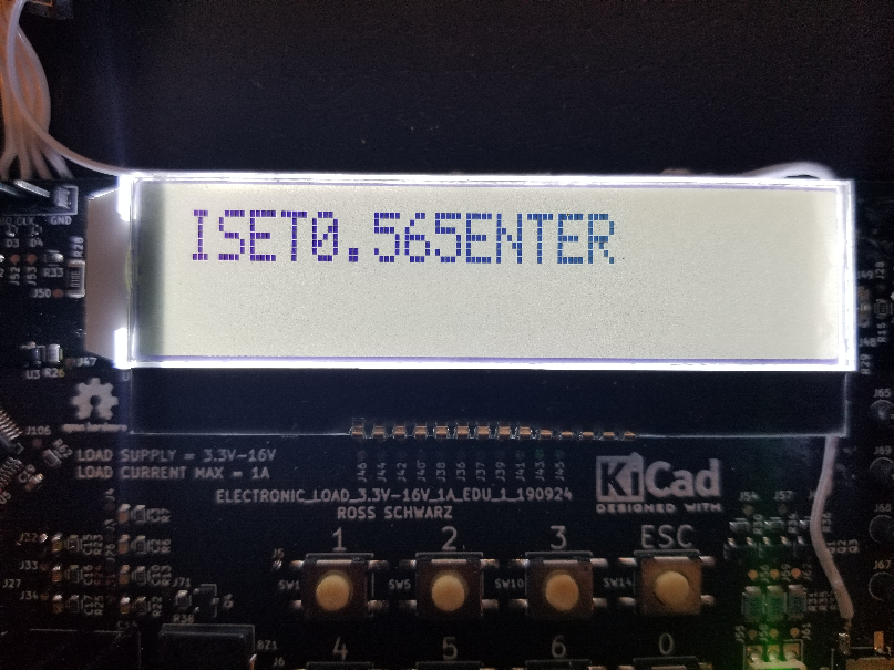
Using the key pad feels great. I had a few other people test it out and they felt the response was good and very user friendly.
One last thing to note is the delay required after each digital output is set high. This is needed in order for the filter capacitor in front of the digital input to fully charge to steady state before reading the digital input. I realized when writing the code that this delay is a little too long for my liking, therefore I plan to update the HW design in order to reduce this required delay. I will be covering this topic in my next project log.
I hope you enjoyed my post. Thank you for reading. Please feel free to leave a comment below.
Thanks again.
Discussions
Become a Hackaday.io Member
Create an account to leave a comment. Already have an account? Log In.