 schwarzrmsu
Sorry for not posting in a while. I just got back from Iceland, and dumped water all over my laptop. I am excited to give and update after a long trip and a laptop covered in rice.
The next challenge that I want to take on is the Digital To Analog Converter (DAC):
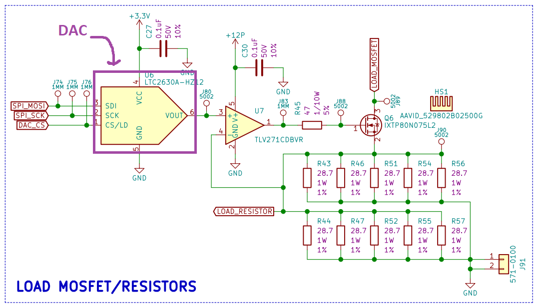
Digital to analog converters are cool devices. DAC's simply output a voltage somewhere between the power and ground reference you provide. The voltage the DAC outputs is based on the message you send it via SPI. This is a 12 bit DAC which means there are the following number of steps:
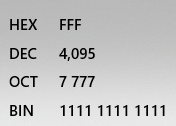
Therefore we have the following resolution between 3.3V and ground:
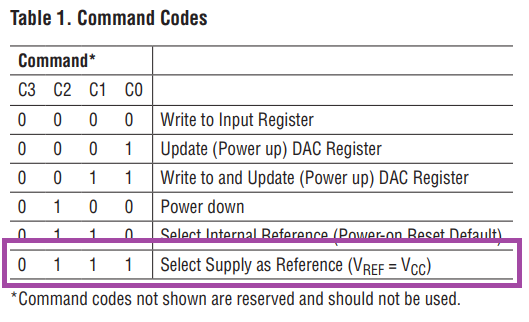
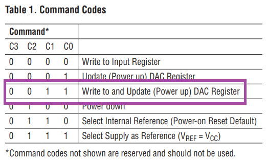
The first thing we are going to do is set the reference voltage to the 3.3V supply we are providing the DAC. This can be done using the following Command Code outlined in the LTC2630 datasheet:
Now that we know the Command Code we need to understand how the rest of the SPI message needs to be structured. The message structure is shown below:
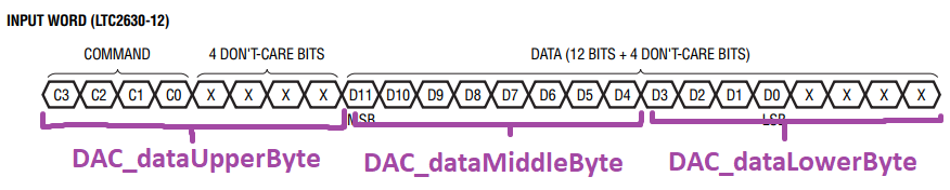
I have broken up the 24 bit message into 3 8-bit variables that I can send in succession.
1. DAC_dataUpperByte_u8
2. DAC_dataMiddleByte_u8
3. DAC_dataLowerByte_u8
For this first message, the DAC is simply going to receive the command code for "Select Supply as Reference" and ignore the rest of the data. Therefore we simply need to package DAC_dataUpperByte with this particular command code, and then send zeros for the remaining bits. The tricky piece is packaging the upper byte. This requires some bit shifting operations. Below is the code that accomplishes this:
uint8_t DAC_selectSupplyAsReferenceCmdCode = 0b0111;

uint8_t DAC_dataUpperByte_u8 = 0b00000000;
uint8_t DAC_dataMiddleByte_u8 = 0b00000000;
uint8_t DAC_dataLowerByte_u8 = 0b00000000;

DAC_dataUpperByte = DAC_selectSupplyAsReferenceCmdCode << 4;
What this code does is takes a uint8_t variable named DAC_dataUpperByte_u8 and sets all bits within the register to 0:

Then we place DAC_selectSupplyAsReferenceCmdCode into DAC_dataUpperByte_u8 register:

Then we shift DAC_selectSupplyAsReferenceCmdCode 4 bits to the left in order to get it into the correct position within the LTC2630 SPI data structure:

Now DAC_dataUpperByte_u8, DAC_dataMiddleByte_u8 & DAC_dataLowerByte_u8 are ready to be sent over the SPI bus from the micro controller to the DAC in order to change the internal reference to our 3.3V supply:
HAL_GPIO_WritePin(DAC_CS_DO_PORT, DAC_CS_DO_PIN, RESET);
HAL_SPI_Transmit(&hspi1, &DAC_dataUpperByte_u8, 1, 10);
HAL_SPI_Transmit(&hspi1, &DAC_dataMiddleByte_u8, 1, 10);
HAL_SPI_Transmit(&hspi1, &DAC_dataLowerByte_u8, 1, 10);
HAL_GPIO_WritePin(DAC_CS_DO_PORT, DAC_CS_DO_PIN, SET);
This code:
1. Pulls the CS pin on the DAC low
2. Sends DAC_dataUpperByte_u8 via SPI
3. Sends DAC_dataMiddleByte_u8 via SPI
4. Sends DAC_dataLowerByte_u8 via SPI
5. Pulls the CS pin the DAC high
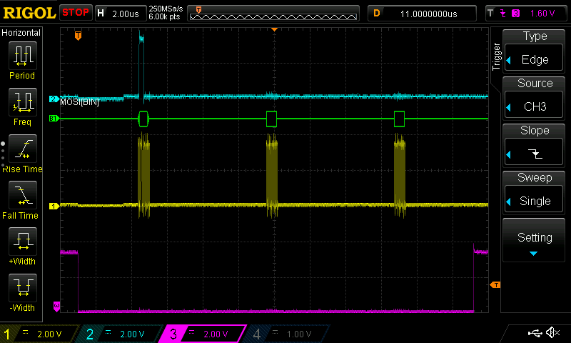
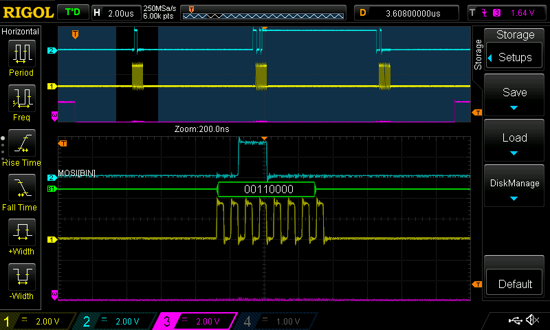
The SPI message can be seen on a scope in the following way:

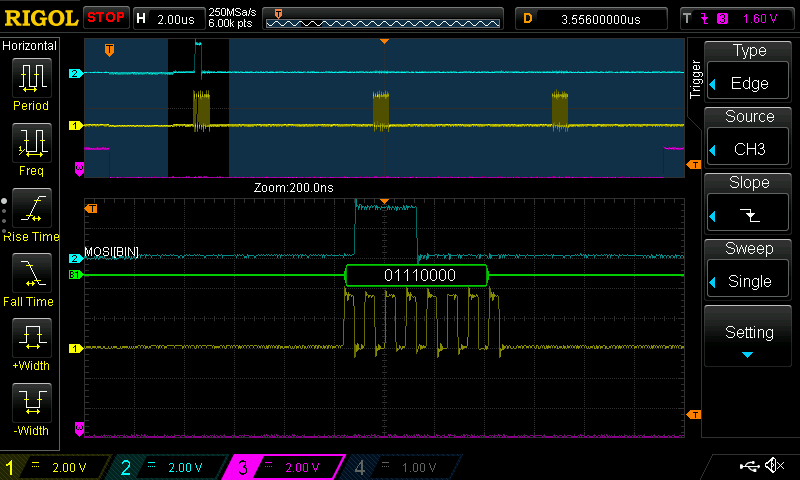
Upper Byte:
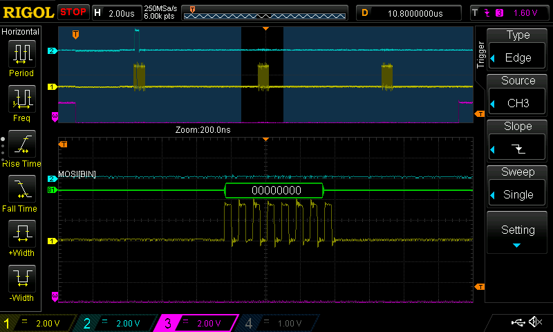
Middle Byte:
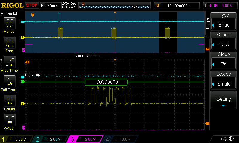
Lower Byte:
Now that we have the reference set, we can set a particular output voltage. For this example we will attempt to set the DAC output voltage to 1.95V.
The first thing we need to do is figure out the command code for setting the output voltage:
Luckily we can use the same bit shifting operation for the upper byte.
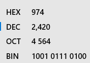
Next we need to figure out the number of counts:
Below is the conversion from 2420 decimal to binary:
This is where things get tricky. We need to take a 12 bit binary message a split it into two bytes named DAC_middleByte_u8 and DAC_lowerByte_u8.
Below is the code for packaging DAC_middleByte_u8:
uint16_t DAC_vSetData_u16 = 0b100101110100;
uint8_t DAC_dataMiddleByte_u8 = 0b00000000;
uint16_t DAC_dataMiddleByte_u16 = 0b0000000000000000;

DAC_dataMiddleByte_u16 = DAC_vSetData_u16 >> 4;
DAC_dataMiddleByte_u8 = DAC_dataMiddleByte_u16;
This code sets DAC_vSetData_u16 with the data to generate 1.95V. Then it initializes an uint8_t DAC_dataMiddleByte_u8 & uint16_t DAC_dataMiddleByte_u16 to a binary value of 0:


Then it takes the contents of DAC_vSetData_u16 and places it inside of DAC_dataMiddleByte_u16:

Then we shift DAC_dataMiddleByte_u16 4 bits to the right in order to get the 8 bits of data we want for DAC_dataMiddleByte_u8 in the first 8 bit positions of DAC_dataMiddleByte_u16:

Now that the relevant data is in the first 8 bits of DAC_dataMiddleByte_u16 we can store its contents into the 8 bit version DAC_dataMiddleByte_u8:

Lastly we need to package DAC_lowerByte_u8. Below is the code for packaging DAC_lowerByte_u8:
uint16_t DAC_vSetData_u16 = 0b100101110100;
uint8_t DAC_dataLowerByte_u8 = 0b00000000;

DAC_dataLowerByte_u8 = DAC_vSetData_u16 & 0b1111;
DAC_dataLowerByte_u8 = DAC_dataLowerByte_u8 << 4;
This uses the same variable DAC_vSetData_u16 with the data to generate 1.95V. Then it initializes an uint8_t DAC_dataLowerByte_u8 to a binary value of 0:


The next step copies the first 4 bits of DAC_vSetData_u16 into the first 4 bits of DAC_dataLowerByte_u8:

Next we shift this data 4 bits to the left in order to match the required data format outlined in the datasheet:

Now DAC_dataUpperByte_u8, DAC_dataMiddleByte_u8 & DAC_dataLowerByte_u8 are ready to be sent over the SPI bus from the micro controller to the DAC in order to change the output voltage to 1.95V. This is the same code we used to set the reference voltage:
HAL_GPIO_WritePin(DAC_CS_DO_PORT, DAC_CS_DO_PIN, RESET);
HAL_SPI_Transmit(&hspi1, &DAC_dataUpperByte_u8, 1, 10);
HAL_SPI_Transmit(&hspi1, &DAC_dataMiddleByte_u8, 1, 10);
HAL_SPI_Transmit(&hspi1, &DAC_dataLowerByte_u8, 1, 10);
HAL_GPIO_WritePin(DAC_CS_DO_PORT, DAC_CS_DO_PIN, SET);
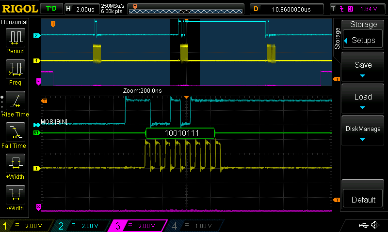
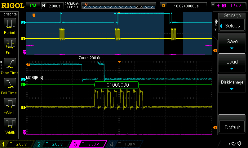
The SPI message can be seen on a scope in the following way:
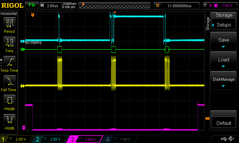
Upper Byte:
Middle Byte:
Lower Byte:
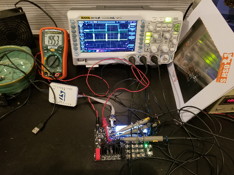
To confirm this works we can simply measure the voltage at the output of the DAC to confirm that 1.95V is present:
Now that we have set a single voltage, we can manipulate DAC_vSetData_u16 and change the output voltage of the DAC. I plan on using it to control the MOSFET in order to generate a steady state current. I will cover this in a later post.
I hope you enjoyed my post. Thank you for reading. Please feel free to leave a comment below.
Thanks again.
Discussions
Become a Hackaday.io Member
Create an account to leave a comment. Already have an account? Log In.