 schwarzrmsu
I have been getting annoyed with my current programming header connections:
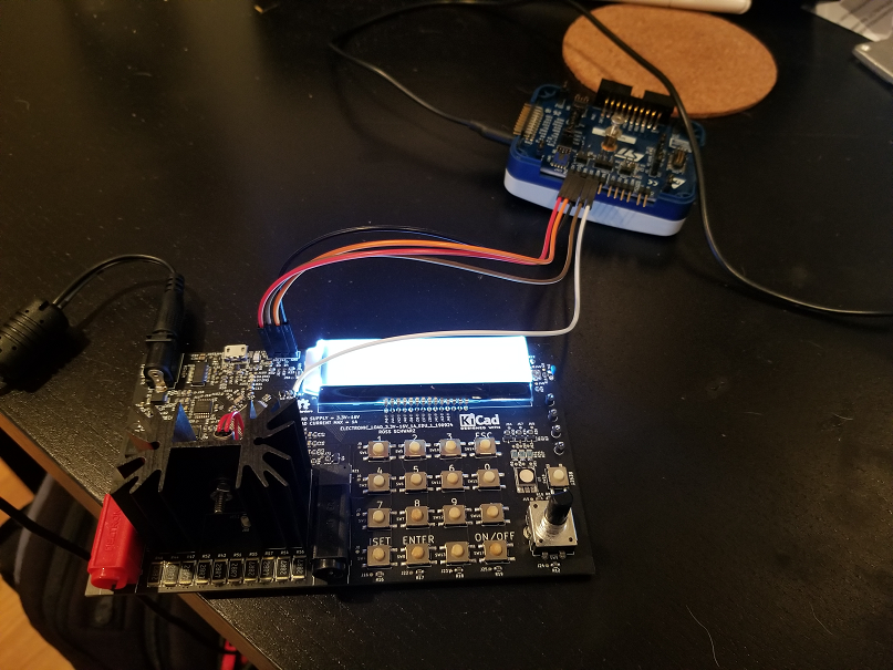
The connections need to be individually un-done and re-done if you want to disconnect the programming tool from the PCB. Therefor i have decided to make an adapter board that would make my programming interface directly compatible with the main 14 pin header on the STLINK-V3:

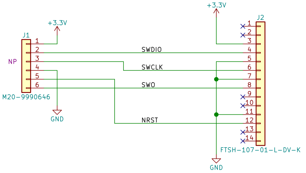
Below is the schematic I created:
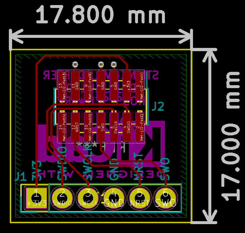
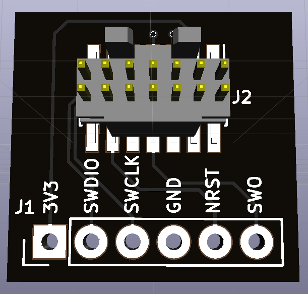
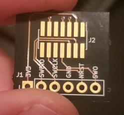
Below is the board I designed:
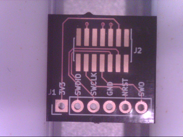
I ordered these boards on OSH Park, and took advantage of the cool "After Dark" option that is currently available:
This board construction is really cool because it uses a dark substrate and a clear soldermask. This makes it look like the copper is exposed, but it is in fact under a layer of clear solder resist material.
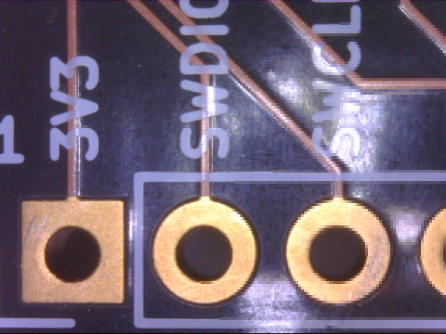
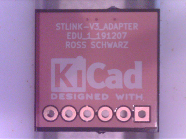
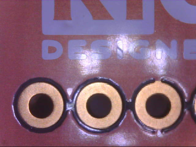
The construction on these boards is really incredible. The copper etching and silk screen definition is insanely good.
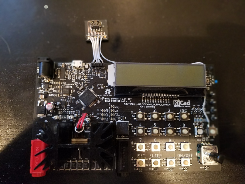
I then soldered the connector to the board, and this jumper board to my PCB:
I then connected to the STLINK-V3 using the 14 way ribbon cable as mentioned earlier:
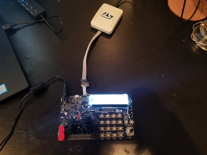
After a quick test, I was able to connect to my micro-controller and successfully flash the micro-controller. This makes disconnecting and reconnecting the STLINK-V3 much easier. This also cleans up my bench setup as well.
Hope you found this interesting. Thanks for reading.
Discussions
Become a Hackaday.io Member
Create an account to leave a comment. Already have an account? Log In.