 schwarzrmsu
In my last post I explained how transitioning from the external 3.3V reference to the internal 4.096V reference will help increase the accuracy of the DAC's output voltage. In this post we are actually going to update the HW and SW in order to transition from the external reference to the internal reference.
In order to use the DAC's internal 4.096V reference, we need to power the DAC from a voltage source that is higher in voltage. Unfortunately the only two voltage rails we currently have available are 12V & 3.3V. 12V is too high for the DAC, and 3.3V is too low to use the internal reference. Therefore we need to add a 5V rail which will be used to power the DAC. 5V is perfect because its higher than 4.096V, and lower than the maximum allowable voltage for the DAC.
This type of update requires a mod board, therefore I designed one. Below is a screen shot of the schematic:
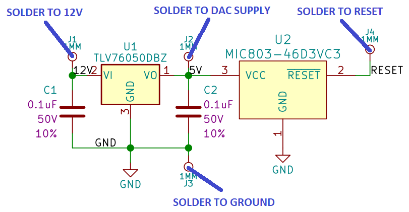
As you can see I am using a simple TLV76050DBZ 5V linear regulator, and I also added in a MIC803-46D3VC3 voltage monitor. The voltage monitor will pull the reset line low when it detects the 5V regulator has dropped out.
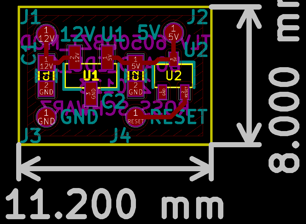
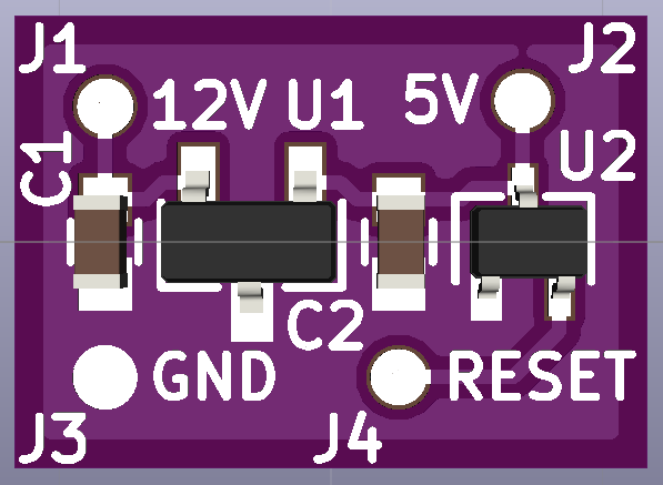
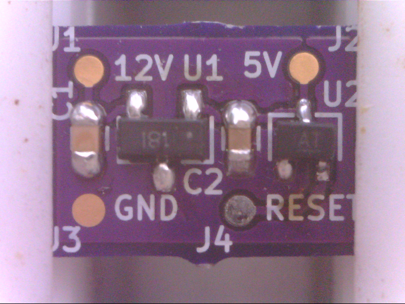
I designed a very small PCB that can be glued to the existing PCBA, and then wired in by soldering wires between mod board and main PCBA. Below are screen shots of the mod board:
Board Layout:
3D Rendering:
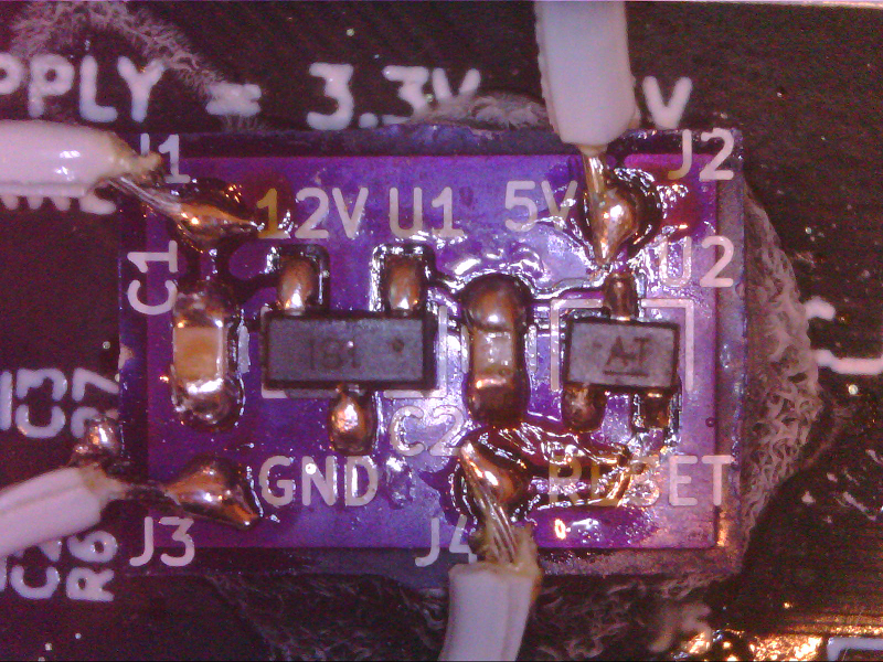
Hand Soldered PCBA:
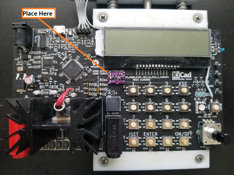
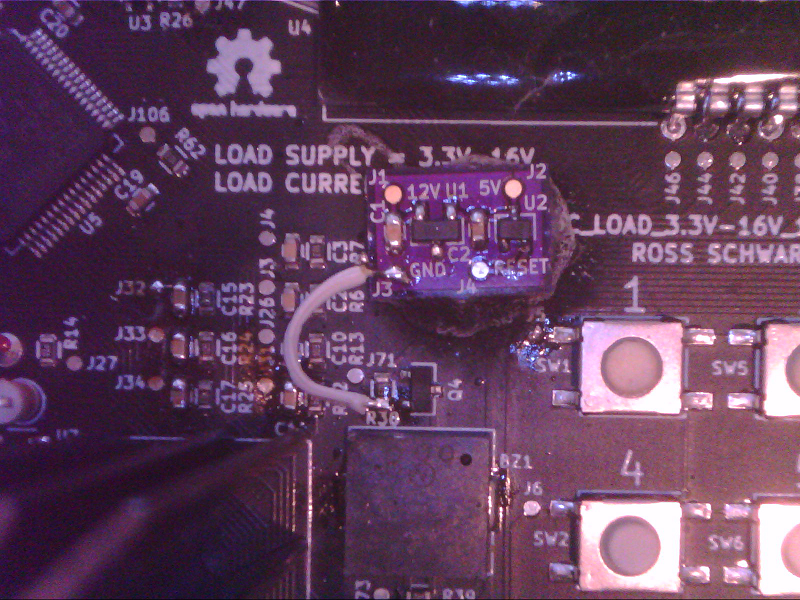
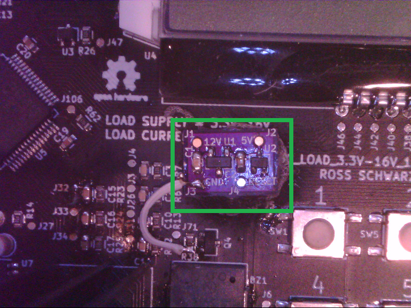
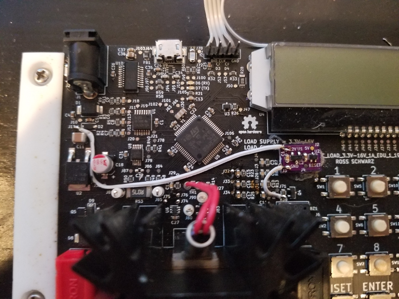
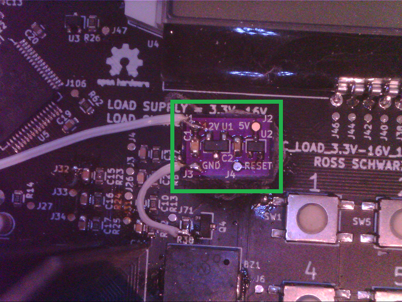
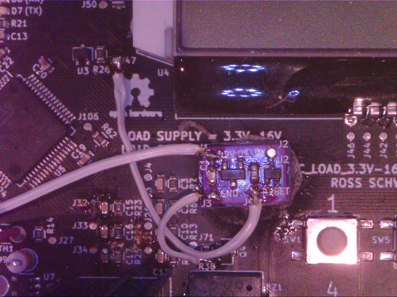
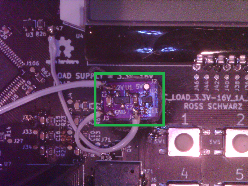
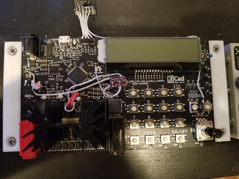
Now we will take this mod board and glue it to the PCBA in an area that does not have any components, and is close to the nets that we need to solder to. Unfortunately I did not have an amazing place, but I settled on this location:
Now we need to wire the mod board to the PCBA. We will need to connect Ground, 12V, Reset and 5V. Below is a walk through on how to do so:
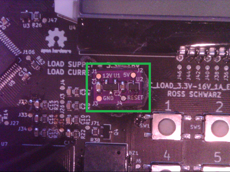
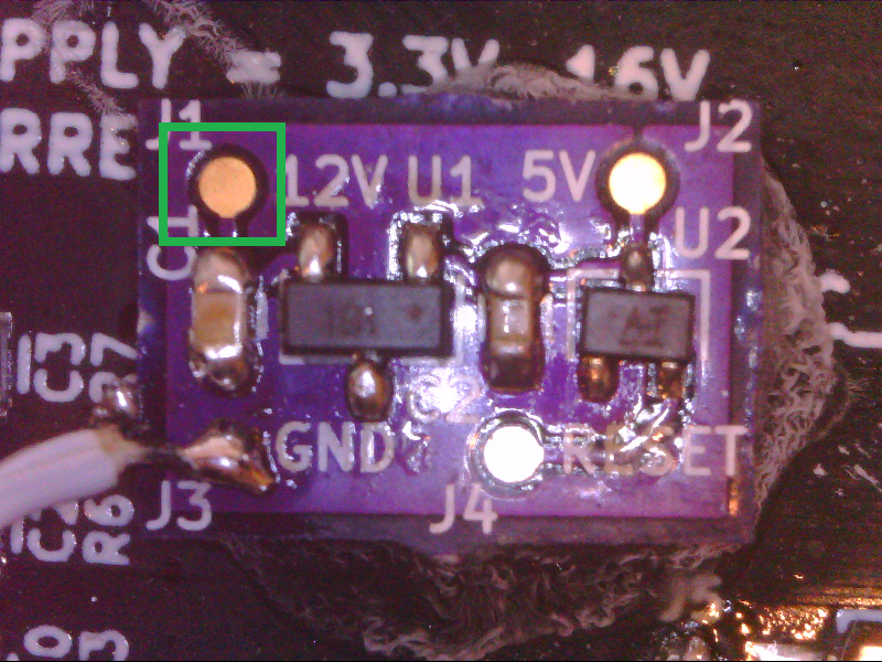
First we are going to route the wire for ground. Locate the mod board PCBA:
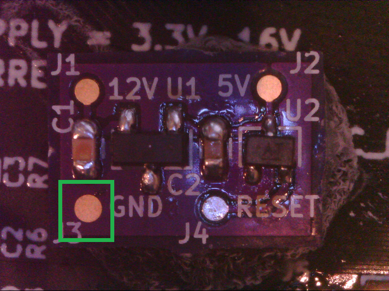
Locate the ground connection on the mod board PCBA:
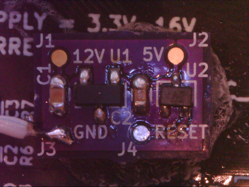
Solder a wire to the ground connection:
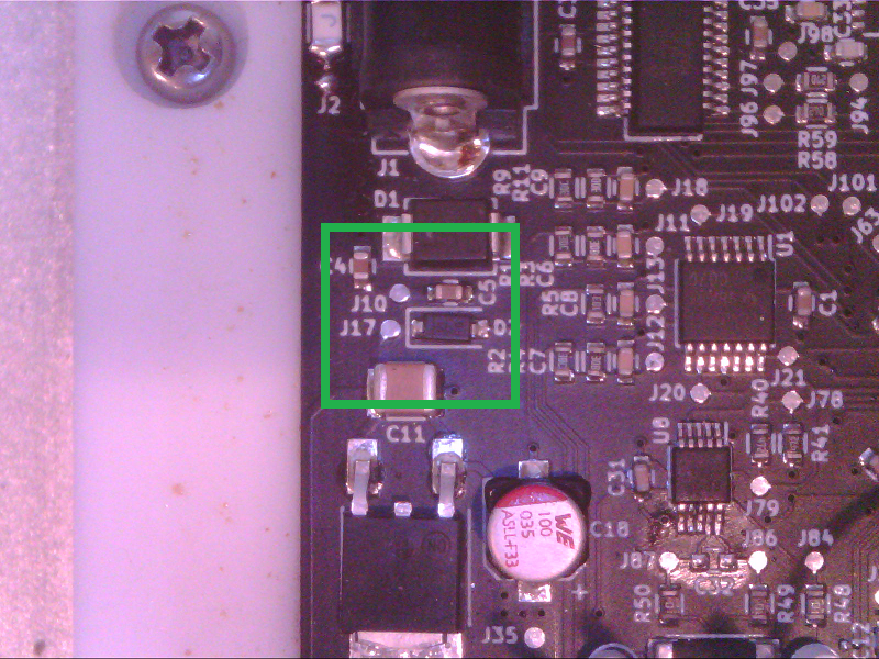
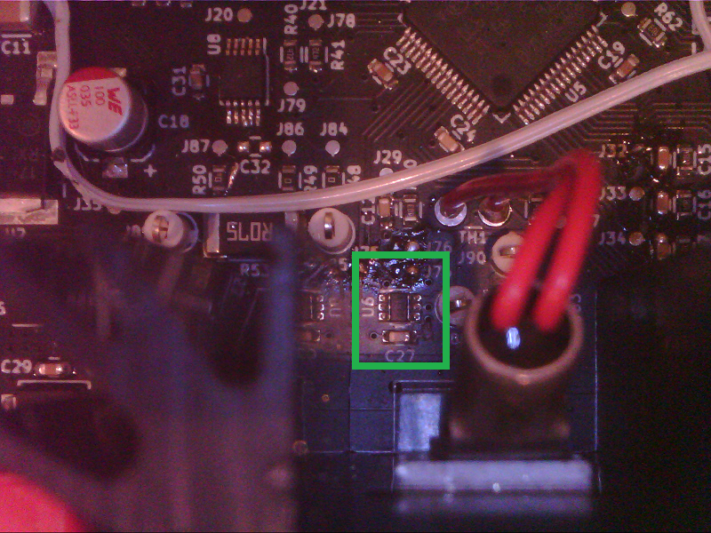
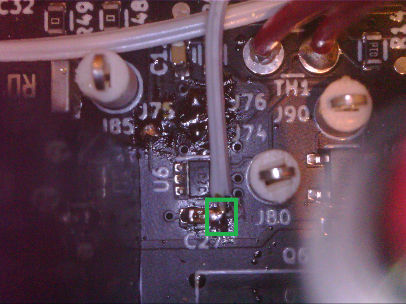
Locate area of main PCBA with ground connection:
Locate ground connection:
Solder other end of wire to ground connection:
Look over ground connection wiring:
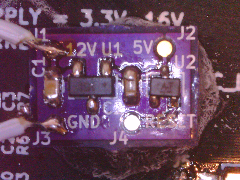
Next we are going to route the wire for 12V. We can start by locating the mod board PCBA:
Locate 12V connection on mod board PCBA:
Solder a wire to the 12V connection:
Locate area of main PCBA with 12V connection:
Locate 12V connection:
Solder other end of wire to 12V connection:
Look over 12V connection wiring:
Next we are going to route the wire for Reset. We can start by locating the mod board PCBA:
Locate reset connection on mod board PCBA:
Solder a wire to the reset connection:
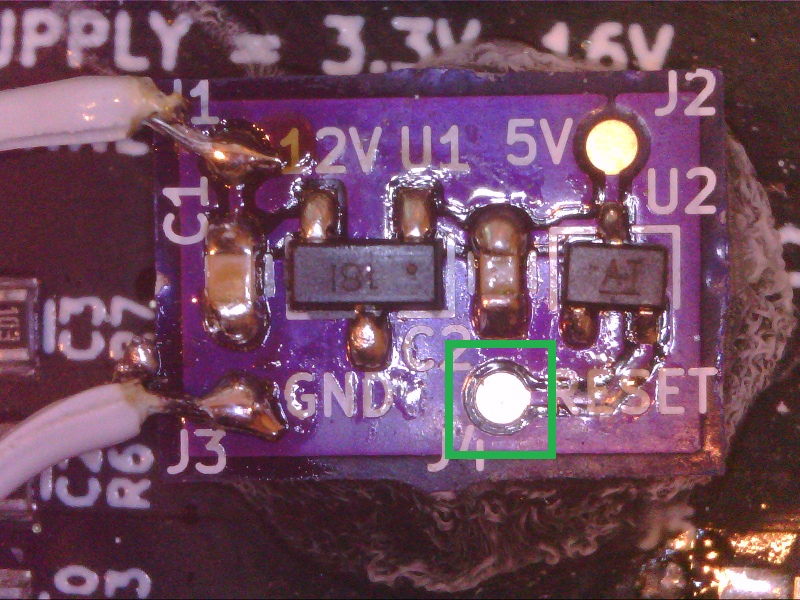
Locate area of main PCBA with reset connection:
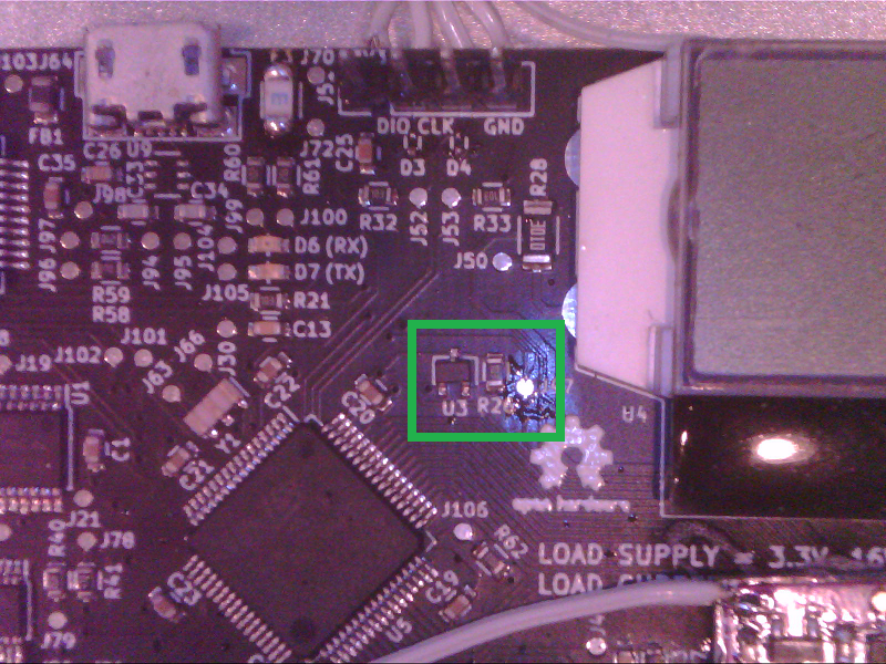
Locate reset connection:
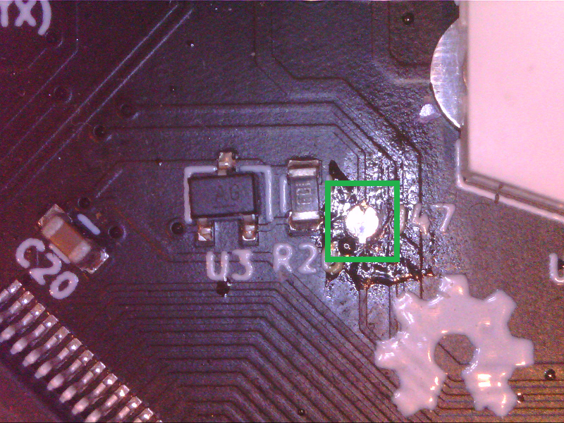
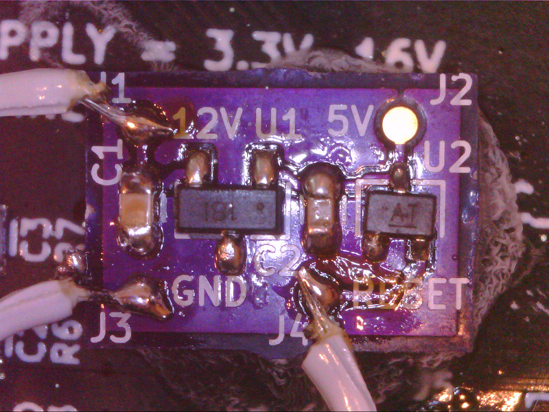
Solder other end of wire to reset connection:
Look over reset connection wiring:
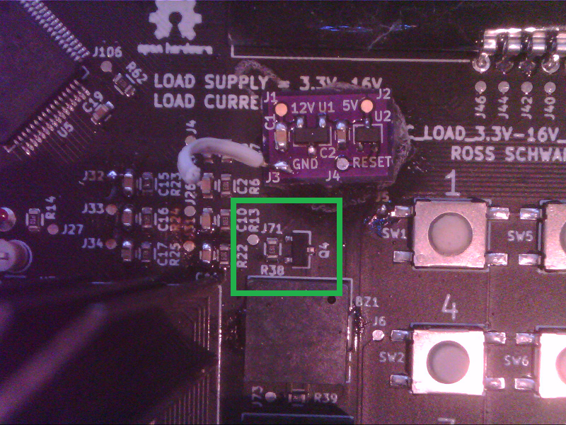
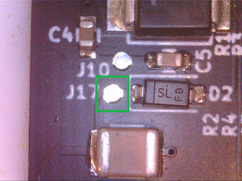
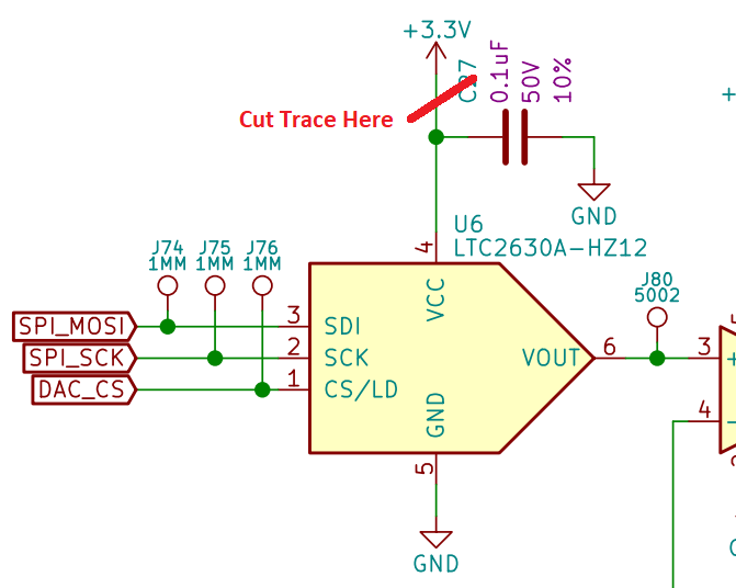
Lastly we are going to route the wire for 5V. First we need to cut the trace that was originally connecting 3.3V to the DAC:
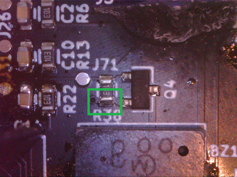
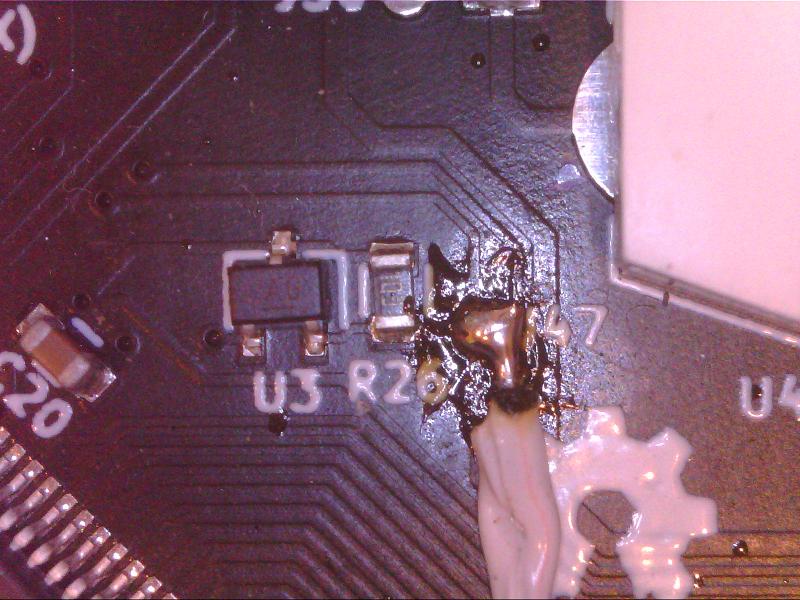
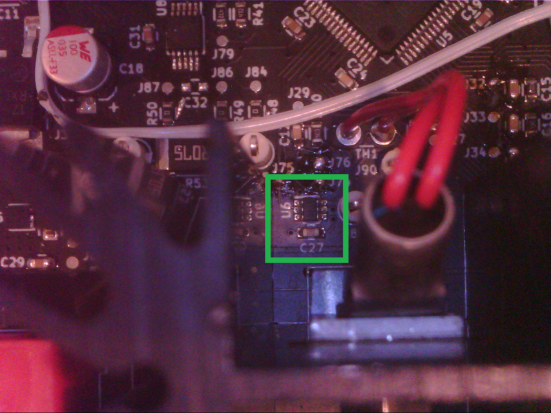
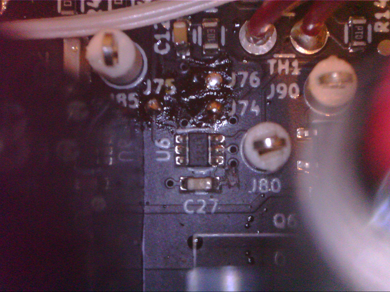
Locate the area of main PCBA with this trace:
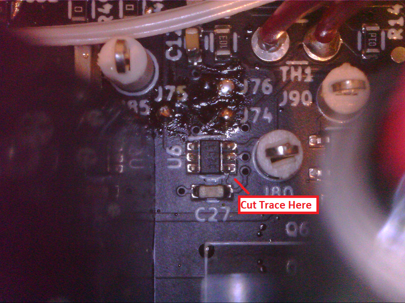
Cut the trace:
Now that the trace is cut, we can route the wire for 5V. We can start by locating the mod board PCBA:
Locate 5V connection on mod board PCBA:
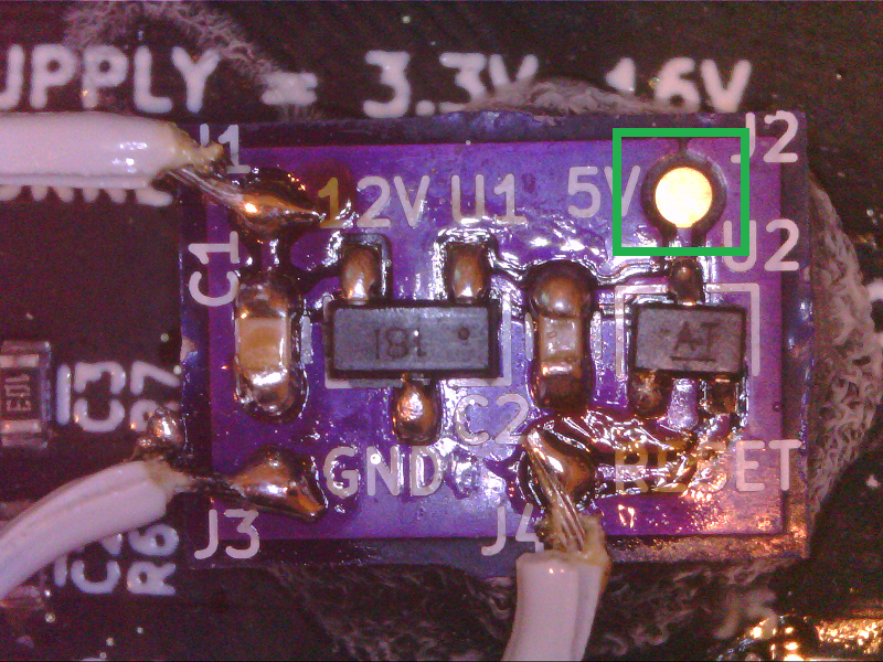
Solder a wire to the 5V connection:
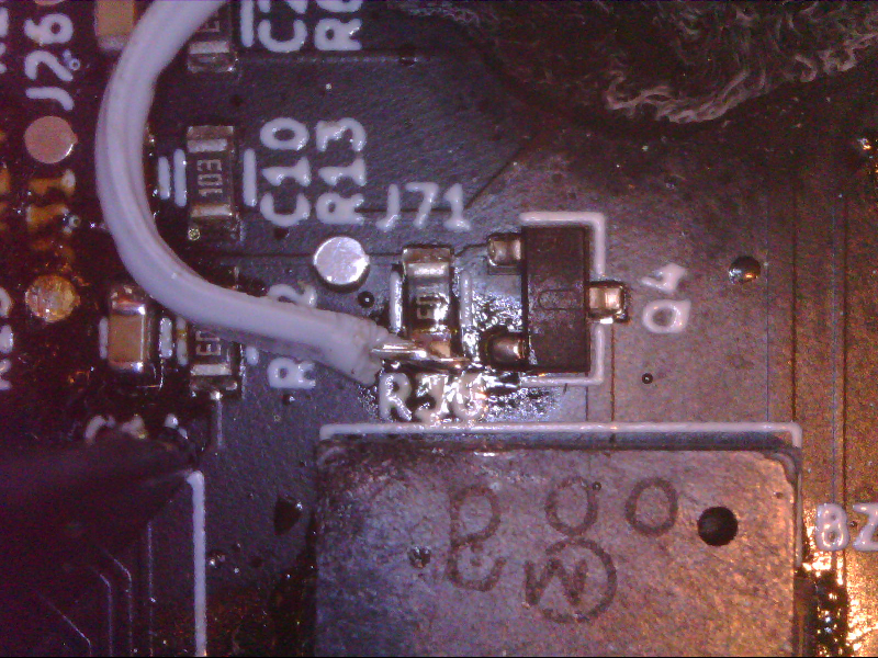
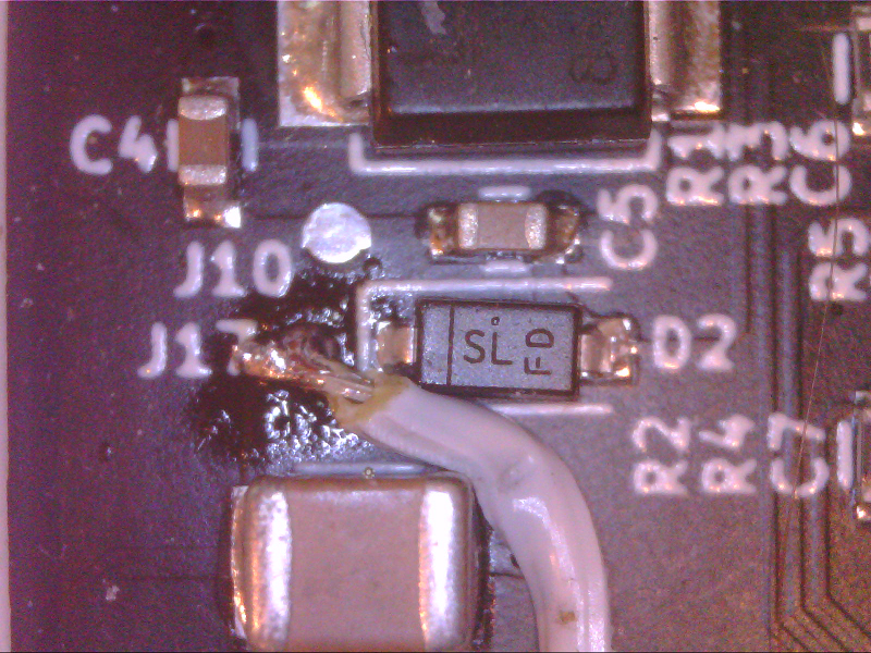
Locate area of main PCBA with 5V connection:
Locate & Solder 5V connection:
Look and review all of the wiring. It is suggested to ring out each connection to check soldering:
Lastly we need to update the SW to use this internal reference. Below is the SW in order to generate 1V at the DAC output:
uint8_t DAC_writeToAndUpdateDACRegisterCmdCode = 0b0011;
uint8_t DAC_selectInternalReferenceCmdCode = 0b0110;

uint16_t DAC_vSetData_u16 = 999;
uint8_t DAC_dataUpperByte_u8 = 0;
uint8_t DAC_dataMiddleByte_u8 = 0;
uint16_t DAC_dataMiddleByte_u16 = 0;
uint8_t DAC_dataLowerByte_u8 = 0;

DAC_dataUpperByte_u8 = DAC_selectInternalReferenceCmdCode << 4;
HAL_GPIO_WritePin(DAC_CS_DO_PORT, DAC_CS_DO_PIN, RESET);
HAL_SPI_Transmit(&hspi1, &DAC_dataUpperByte_u8, 1, 10);
HAL_SPI_Transmit(&hspi1, &DAC_dataMiddleByte_u8, 1, 10);
HAL_SPI_Transmit(&hspi1, &DAC_dataLowerByte_u8, 1, 10);
HAL_GPIO_WritePin(DAC_CS_DO_PORT, DAC_CS_DO_PIN, SET);

DAC_dataUpperByte_u8 = DAC_writeToAndUpdateDACRegisterCmdCode << 4;
DAC_dataMiddleByte_u16 = DAC_vSetData_u16 >> 4;
DAC_dataMiddleByte_u8 = DAC_dataMiddleByte_u16;
DAC_dataLowerByte_u8 = DAC_vSetData_u16 & 0b1111;
DAC_dataLowerByte_u8 = DAC_dataLowerByte_u8 << 4;

HAL_GPIO_WritePin(DAC_CS_DO_PORT, DAC_CS_DO_PIN, RESET);
HAL_SPI_Transmit(&hspi1, &DAC_dataUpperByte_u8, 1, 10);
HAL_SPI_Transmit(&hspi1, &DAC_dataMiddleByte_u8, 1, 10);
HAL_SPI_Transmit(&hspi1, &DAC_dataLowerByte_u8, 1, 10);
HAL_GPIO_WritePin(DAC_CS_DO_PORT, DAC_CS_DO_PIN, SET);
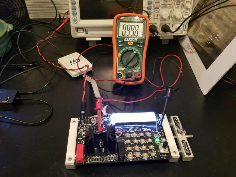
Once the HW and SW updates were complete, I probed the output of the DAC to confirm 1V is present:
I hope you enjoyed my post. Thank you for reading. Please feel free to leave a comment below.
Thanks again.
Discussions
Become a Hackaday.io Member
Create an account to leave a comment. Already have an account? Log In.