0%
0%
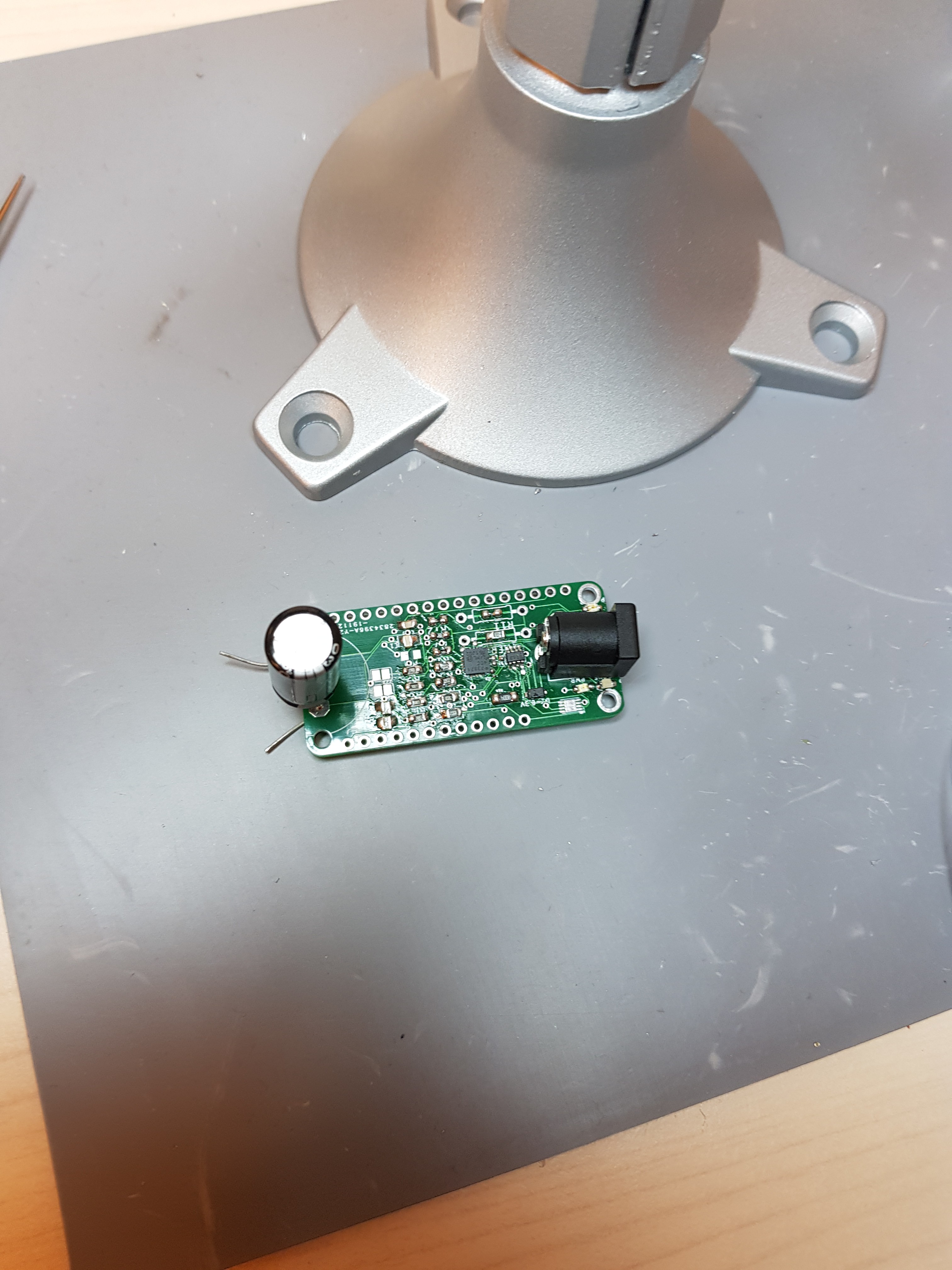
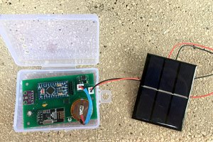
Feather Solar Wing
With a DC barrel connector, you can use this wing to power your feathers, measure solar current and keep track of charge with a fuel gauge.
 axel mansson
Become a Hackaday.io member
Already have an account? Log in.
Just one more thing
To make the experience fit your profile, pick a username and tell us what interests you.
Pick an awesome username
hackaday.io/
Your profile's URL: hackaday.io/username. Max 25 alphanumeric characters.
Pick a few interests
Projects that share your interests
People that share your interests
 Gos
Gos
 David Watts
 DrYerzinia
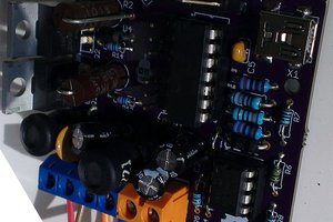
 Gorky
Gorky