 lion mclionhead
The lion kingdom was pondering how to extend the multivibrator into a more sophisticated display & it led to a 9 state animation with 5mm LED's placed side by side, the way lions envisioned such things 40 years ago. Microcontrollers would have been expensive. A fully equipped hobbyist would have done it with TTL logic, in those days.
Lions only knew about BJT's. Lions didn't know the values or how to connect them. What if the way lions envisioned doing it 40 years ago was actually possible?
The heart of the animation is a sequencer. A sequencer for 9 LED states can be made out of 7 delay circuits. It would take far less components than a shift register out of BJTs.
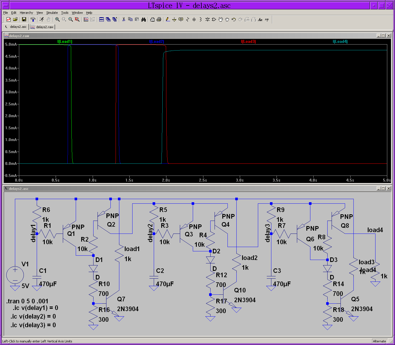
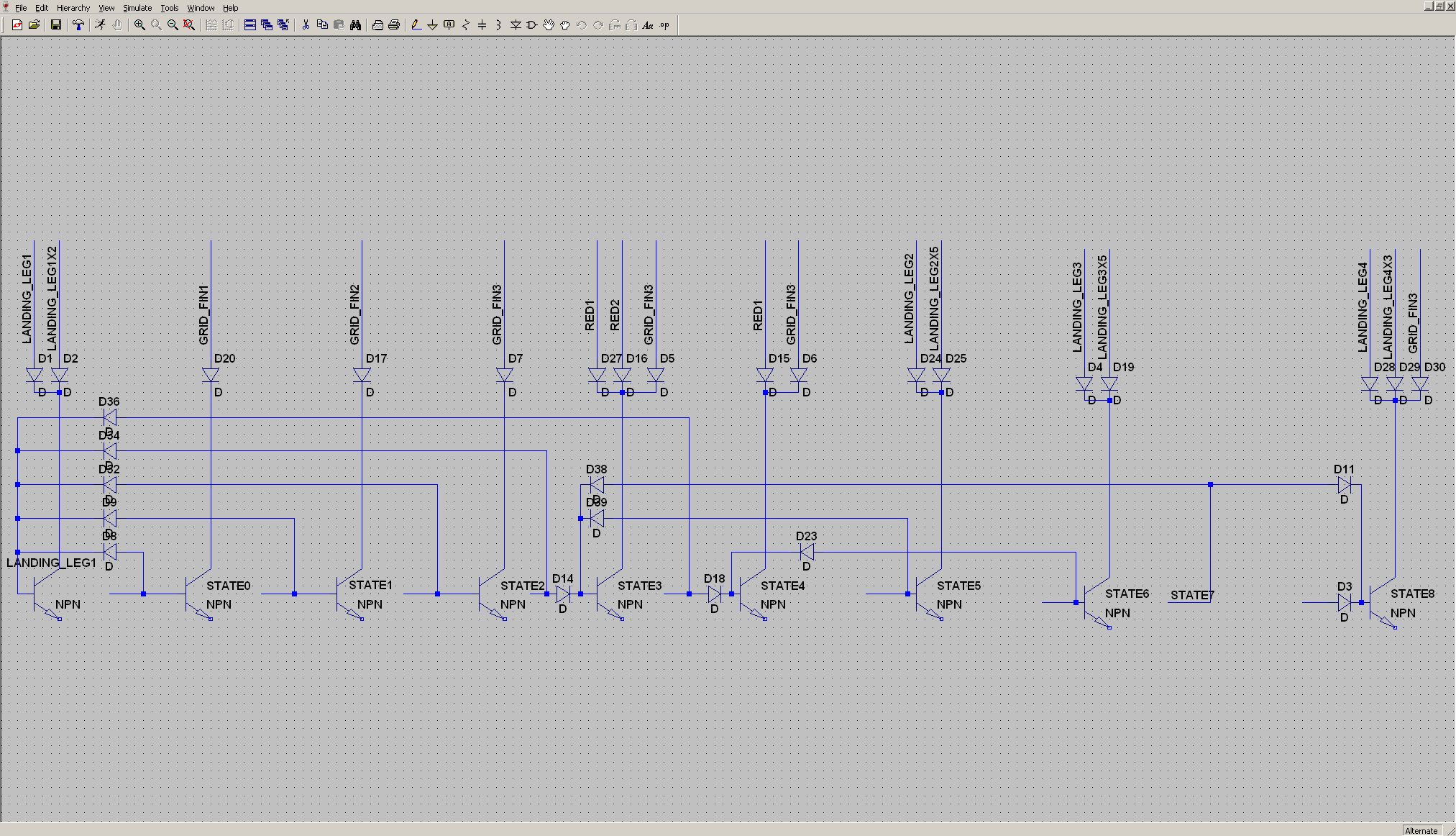
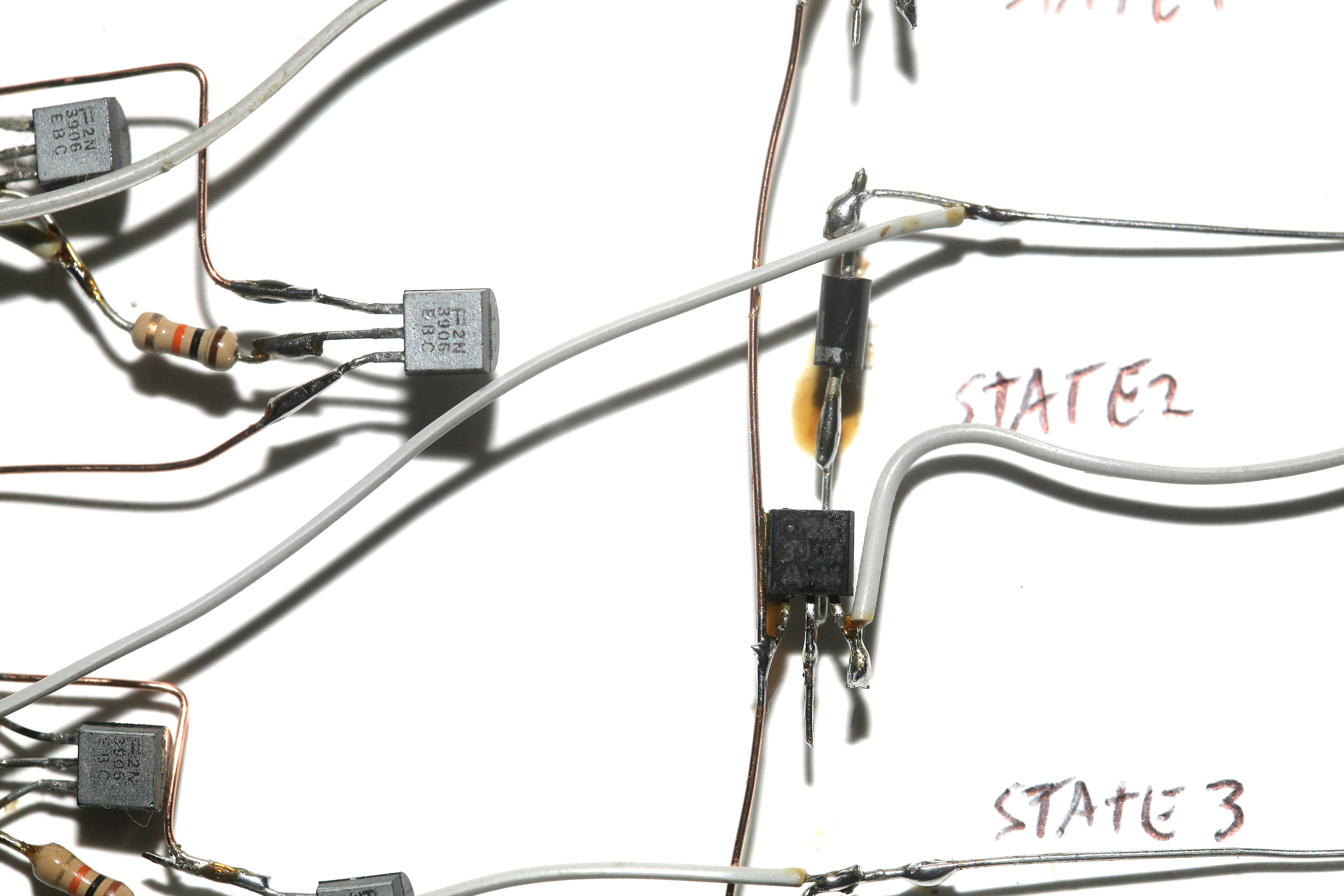
The 700/300 resistors & 2N3904's comprise the switches that turn on the LED strings. The loads are enabled though diodes so multiple states can turn on the same LED strings.
C1, R1, R6, Q1 is the delay circuit which turns on the load. A capacitor C1 slowly raises the base voltage of the load transistor Q1 until it shuts off. The capacitor asymptotically approaches the base cutoff voltage but never quite reaches it, so it needs R6 to pull the voltage up to the rails.
With the load diode D1 no longer receiving current from the delay transistor Q1, a tiny current from the base of Q2 is now drawn to feed the load & Q2 turns on to turn on the next delay module.
The load diode gets a big current from Q1 or a little current from Q2, but always gets some current. The idea that anything is turning off is only an illusion.
The load switch Q7 turns on the LED string when there's a big current & turns off the LED string when there's a little current. This selectivity is created by a 700/300 resistor divider. With little current, the 300 voltage is below the base voltage so the transistor turns off. With big current, the 300 voltage is above the base voltage so the transistor turns on.
The trick is the delay transistor Q1 starts turning off when the capacitor voltage hits 4.5V, then some time later the Q1 transistor completely turns off, the load switch Q7 hits 0.5V & turns off the LED string. The gap between the 2 transistors has to be narrowed by raising the cutoff voltage of the LED switch Q7 closer to 4.5V. The resistor divider raises the cutoff voltage by presenting 0.5V to the base when it receives 4.5V.
The resistor ratio depends on how much current the load switch needs to turn on, so it's a finicky tongue angle adjustment. The delay sequencer can't be tested without the loads. Such are the interdependencies of a minimal component, historic design.
After the last delay circuit has fired, we need a 0V reset pulse to ground all the capacitors & restart the sequencer. The 0V pulse comes from a multivibrator. With a 0V pulse, the final LED string doesn't need a delay since the reset pulse will stop it. Also with the 0V pulse, the 1st delay circuit doesn't need the capacitor C1 or the pullup R6. The reset pulse can turn on & off the delay transistor Q1 directly.
Since brightness wasn't a priority, all the LEDs could be obtaned from a cheap kit.
https://www.amazon.com/Emitting-Assortment-Diffused-Yellow-Colors/dp/B07DQQCXV9/
Of course, if you're going to spend months paw soldering 210 LEDs, they might as well be jumbo sized.
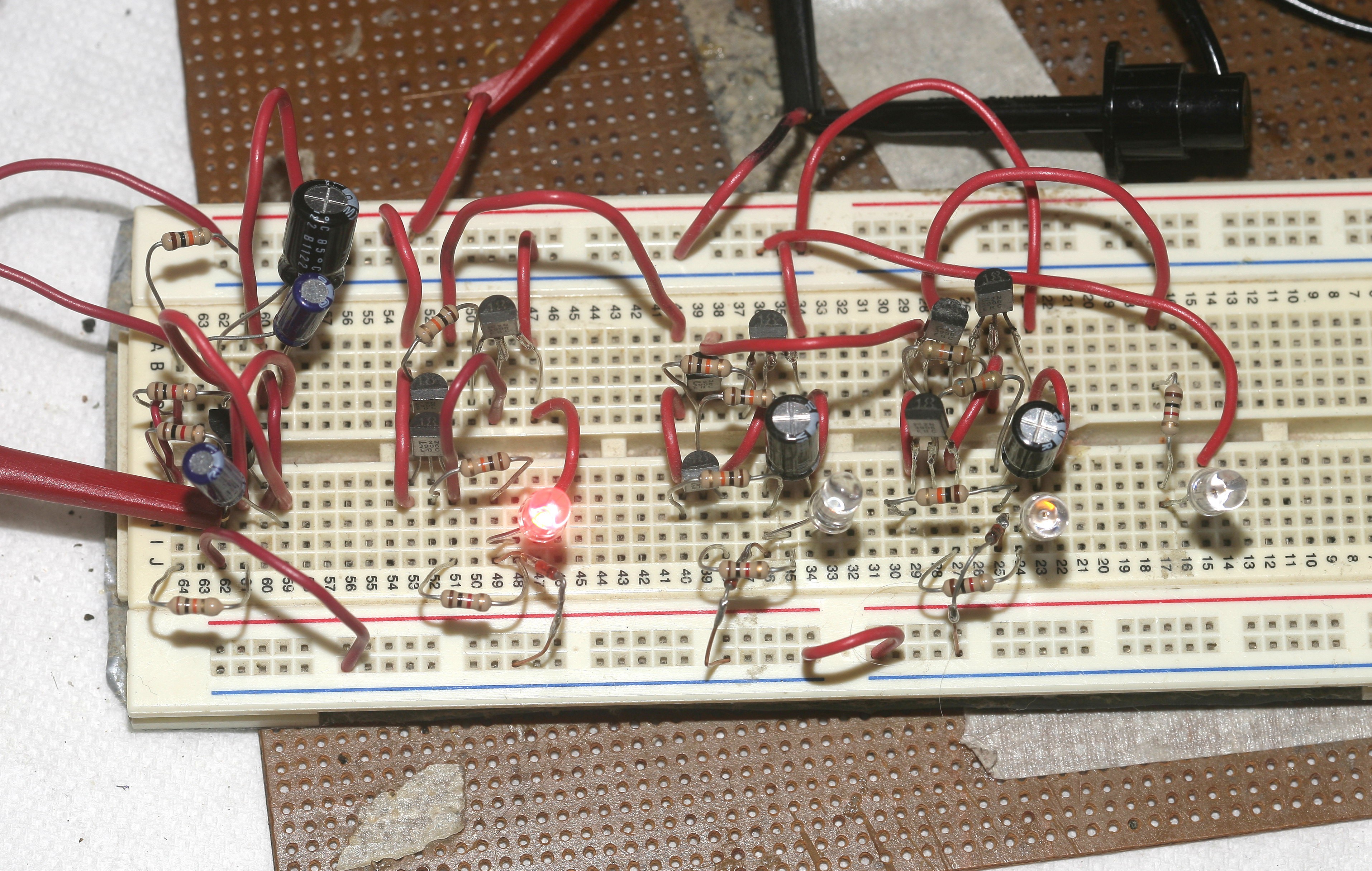
Early sequencer on a breadboard for checking delays.
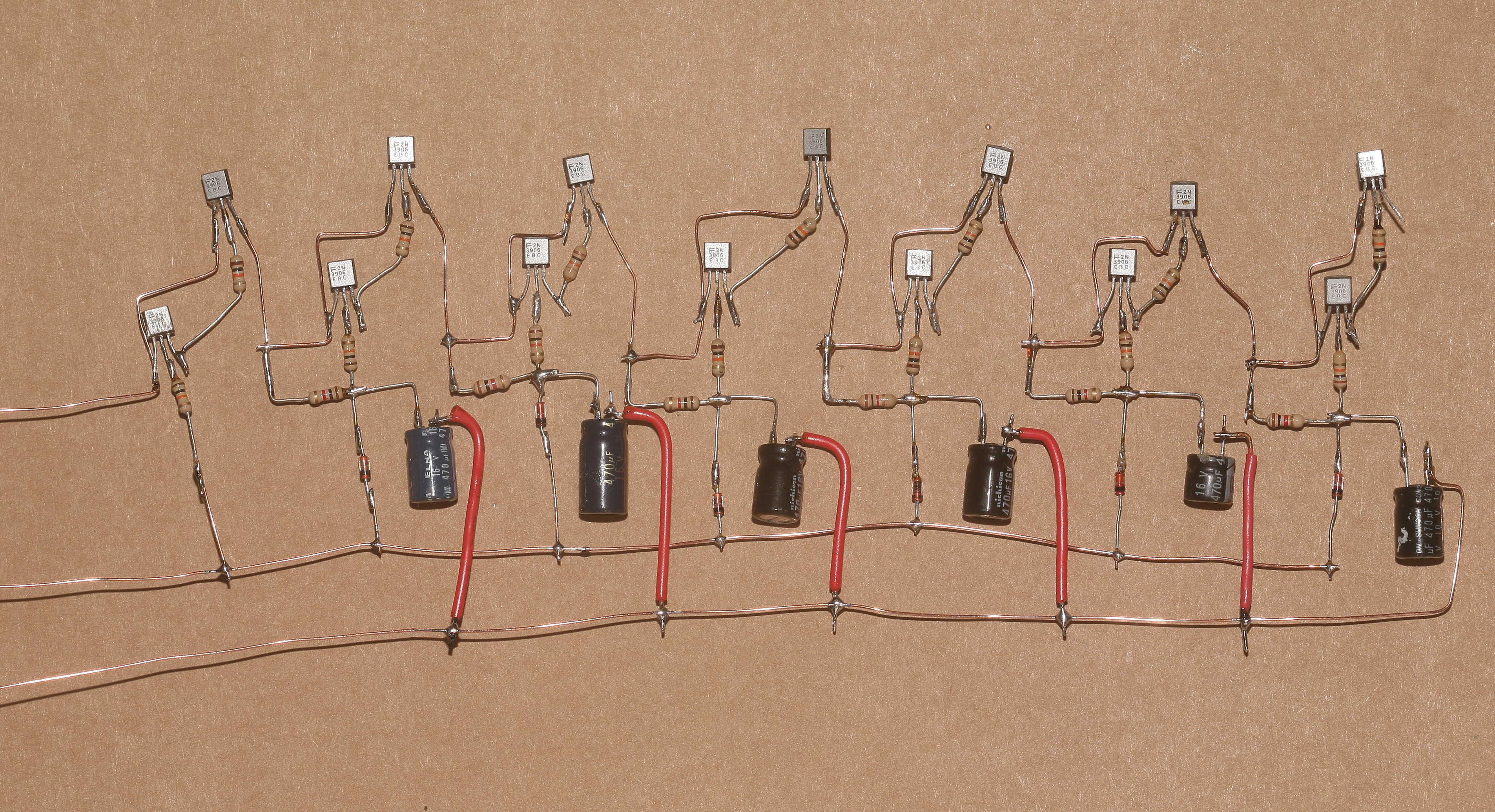
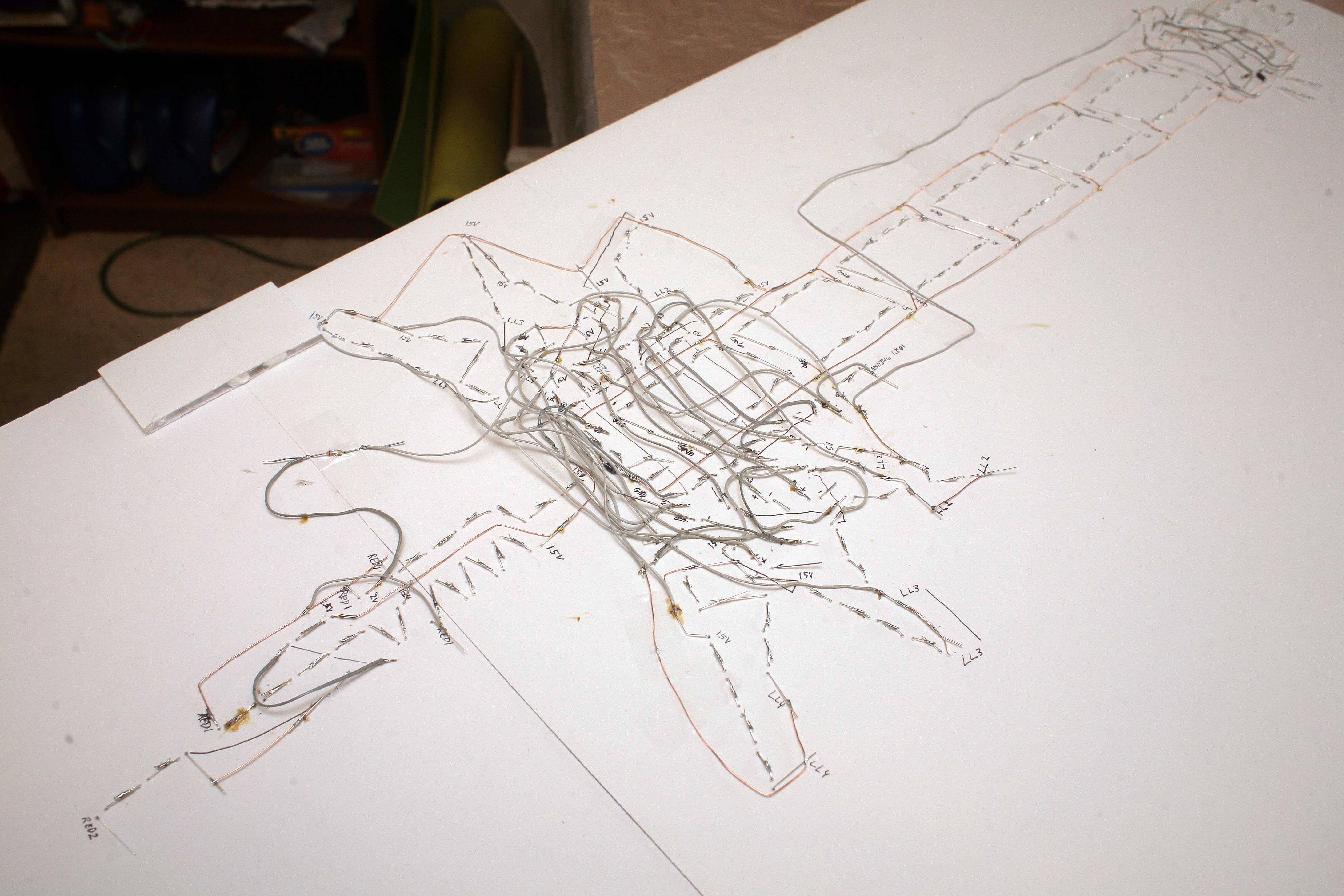
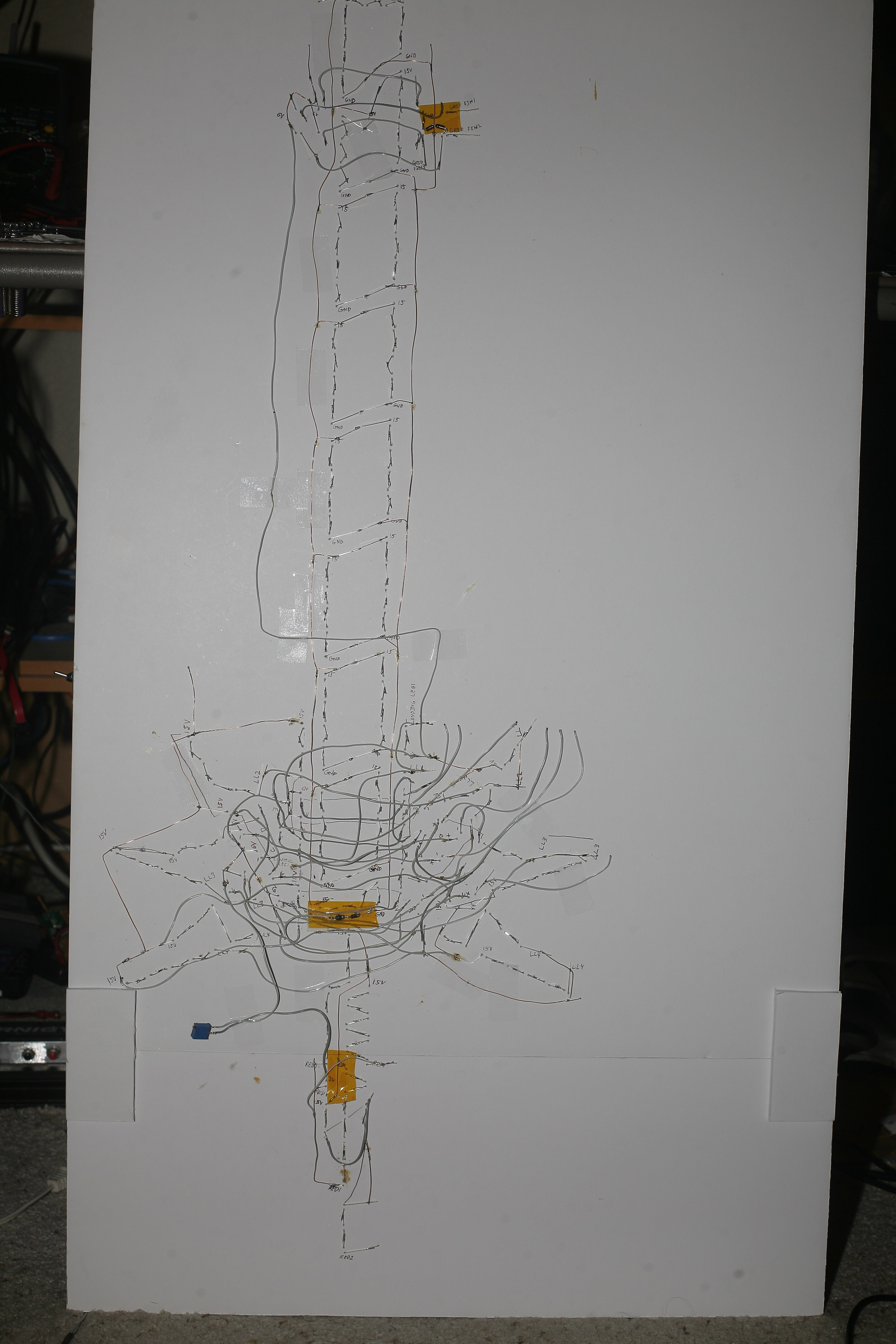
The sequencer was fabricobbled point to point, as it would have been done 40 years ago, to make a living schematic with all its wiring visible.
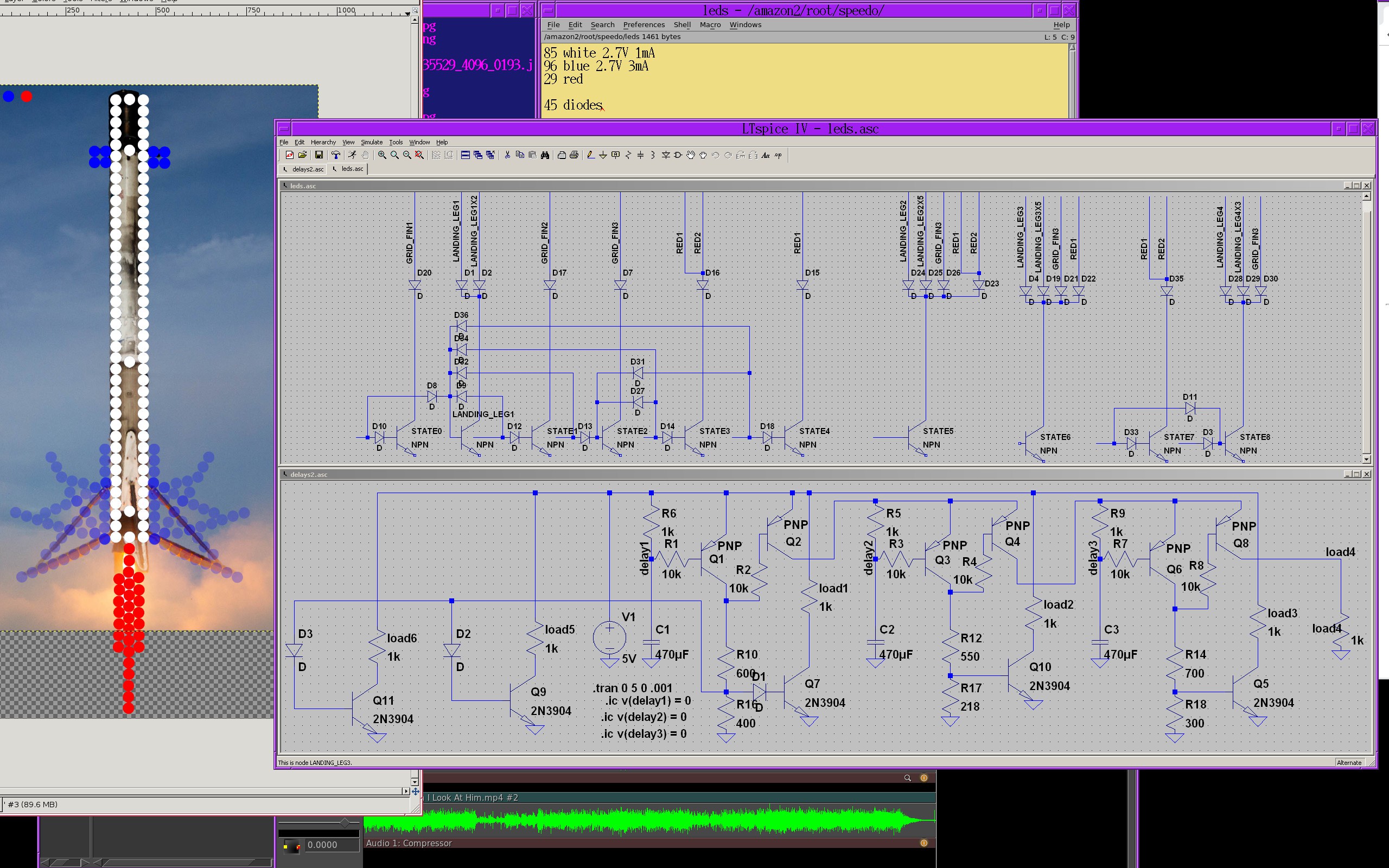
When it came time to translate the 9 sequencer states to the LED voltages, the insanity of trying to do it in analog began to escalate. The 1st problem is it would take hundreds of diodes to fabricate a memory device capable of switching on the right LEDs in the right states. This could be simplified down to 45 diodes by offloading some of the memory to more BJT's. Now the 9 different loads would supply different numbers of transistors so the voltage dividers & the delay resistors would all have to be different.
Furthermore, each stage of the sequencer gets less voltage, until the last stage gets 4V, further altering the voltage divider settings. A modern microcontroller would make all this complexity go away & be done in a few days instead of a few months.
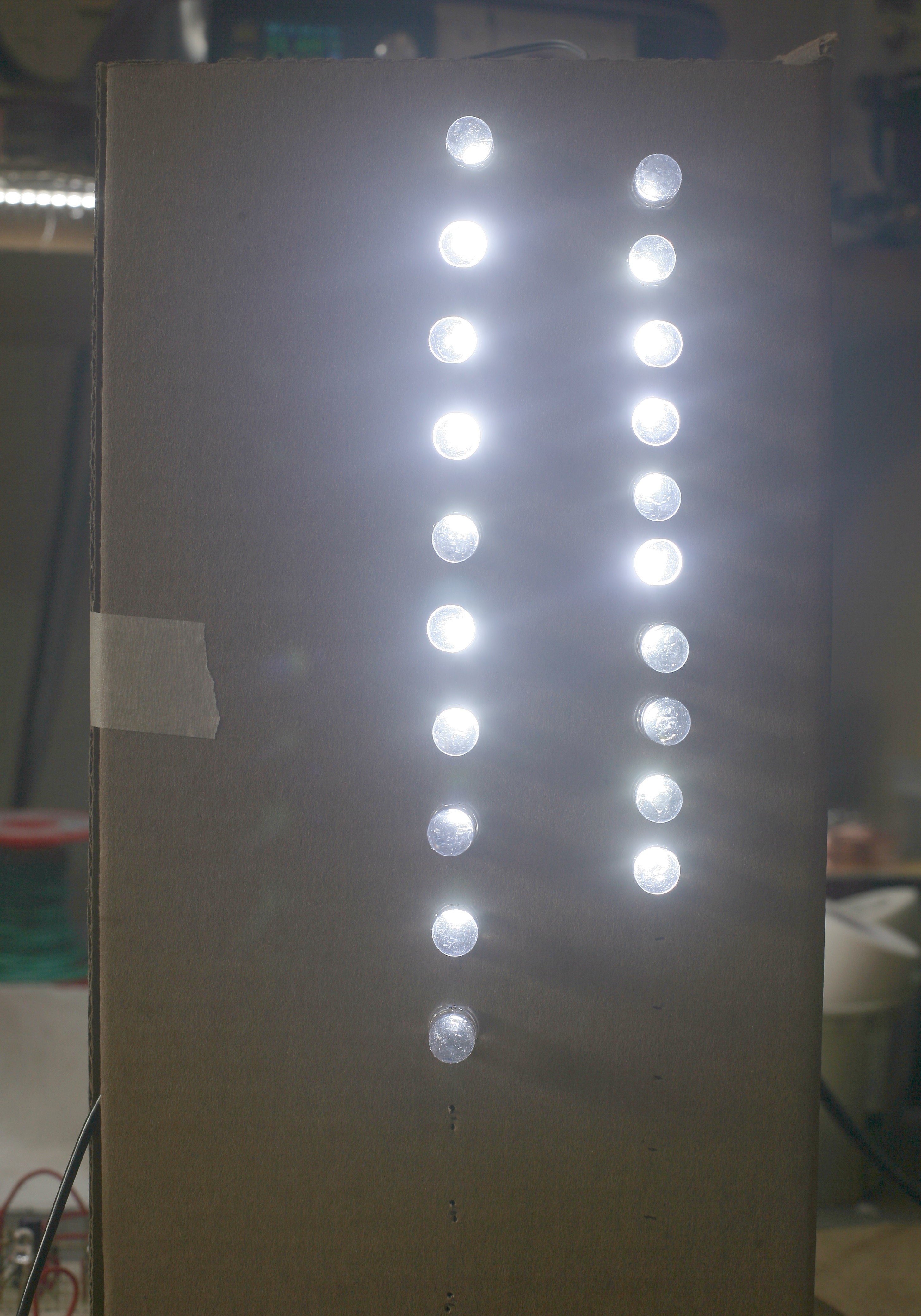
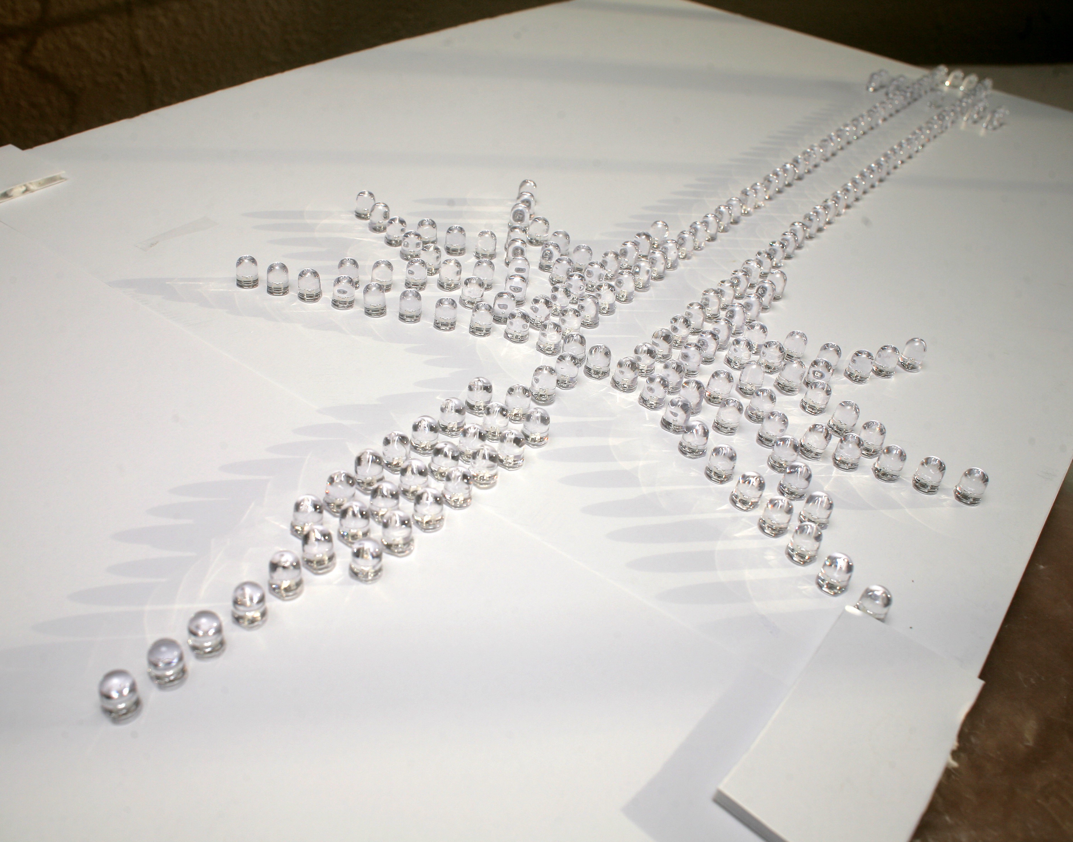
The childhood vision was a line of LEDs stacked as close together as possible, but in the interest of getting a larger display for less money, the LEDs would be spaced. A test of 20mm & 15mm spacing showed the line was harder to detect with 20mm spacing. 20mm spacing would also be too big to fit in the apartment.
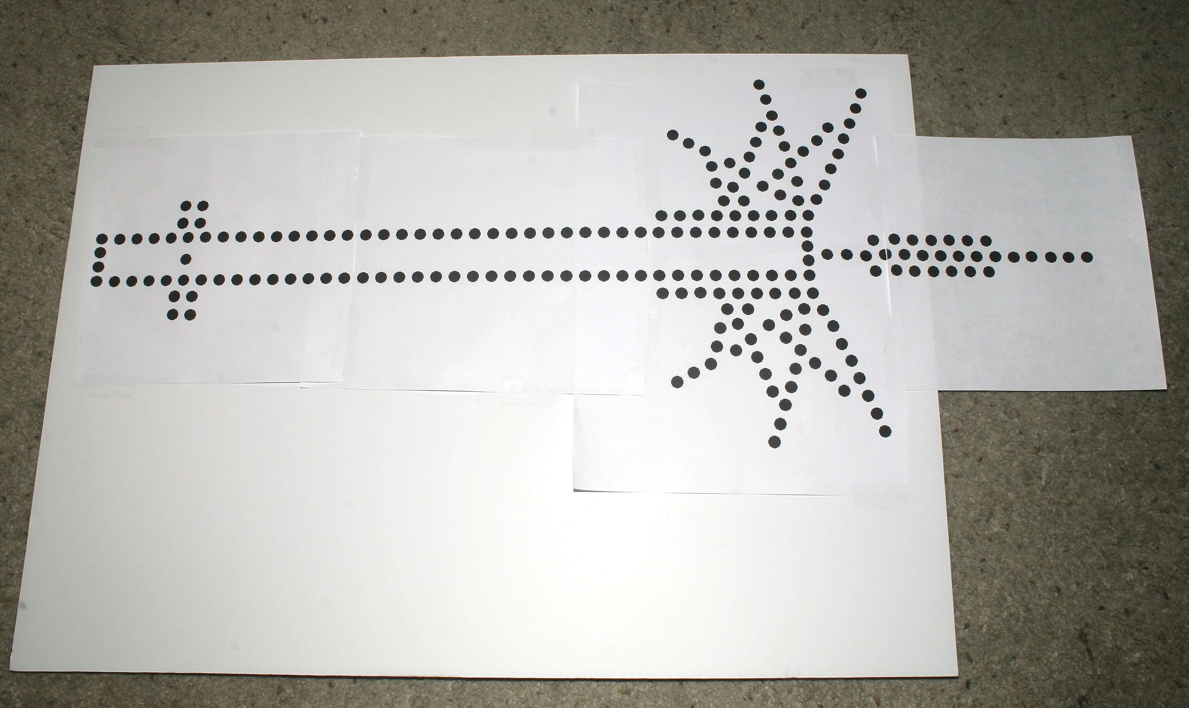
Down went the LED printout with 15mm spacing.
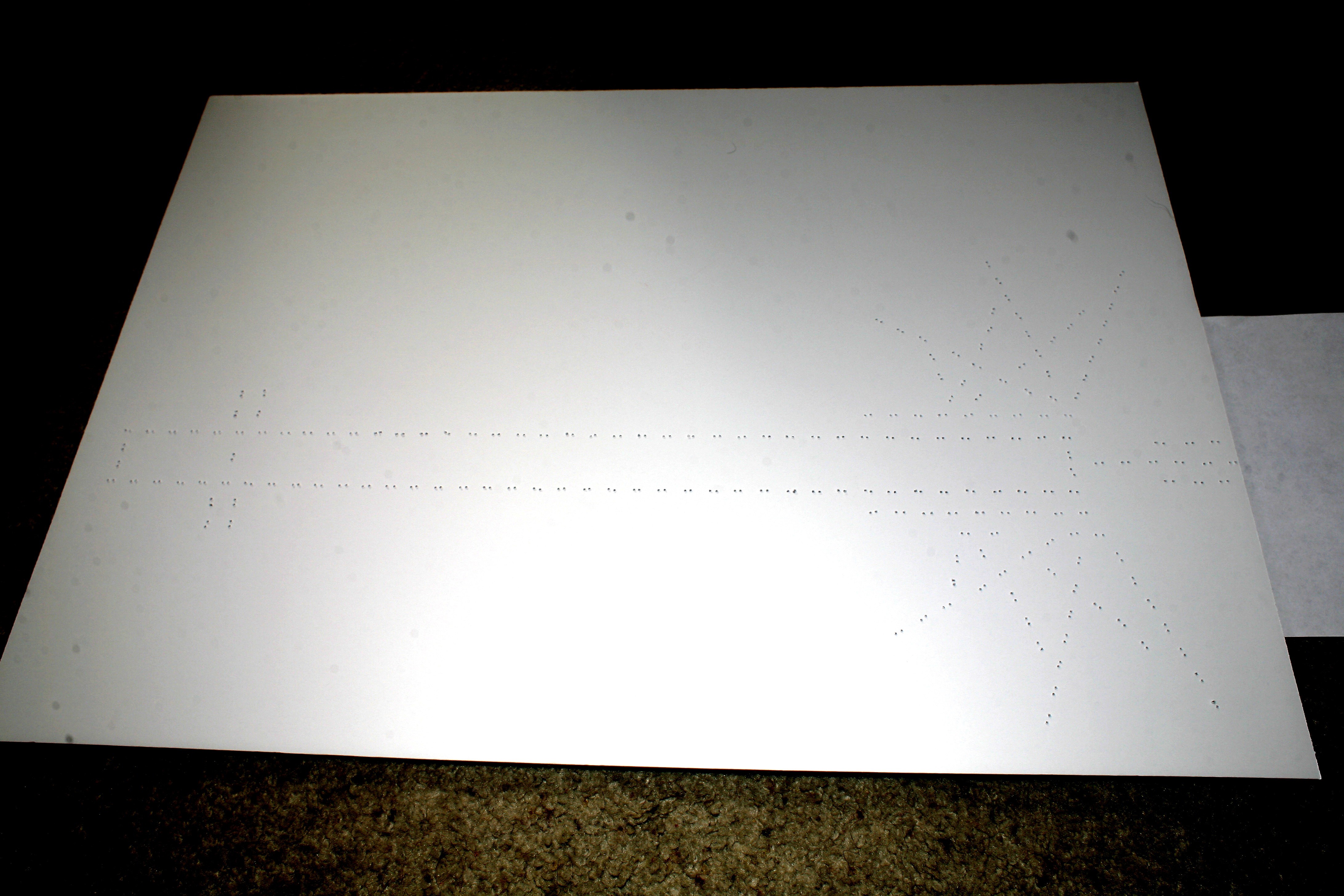
Holes poked.
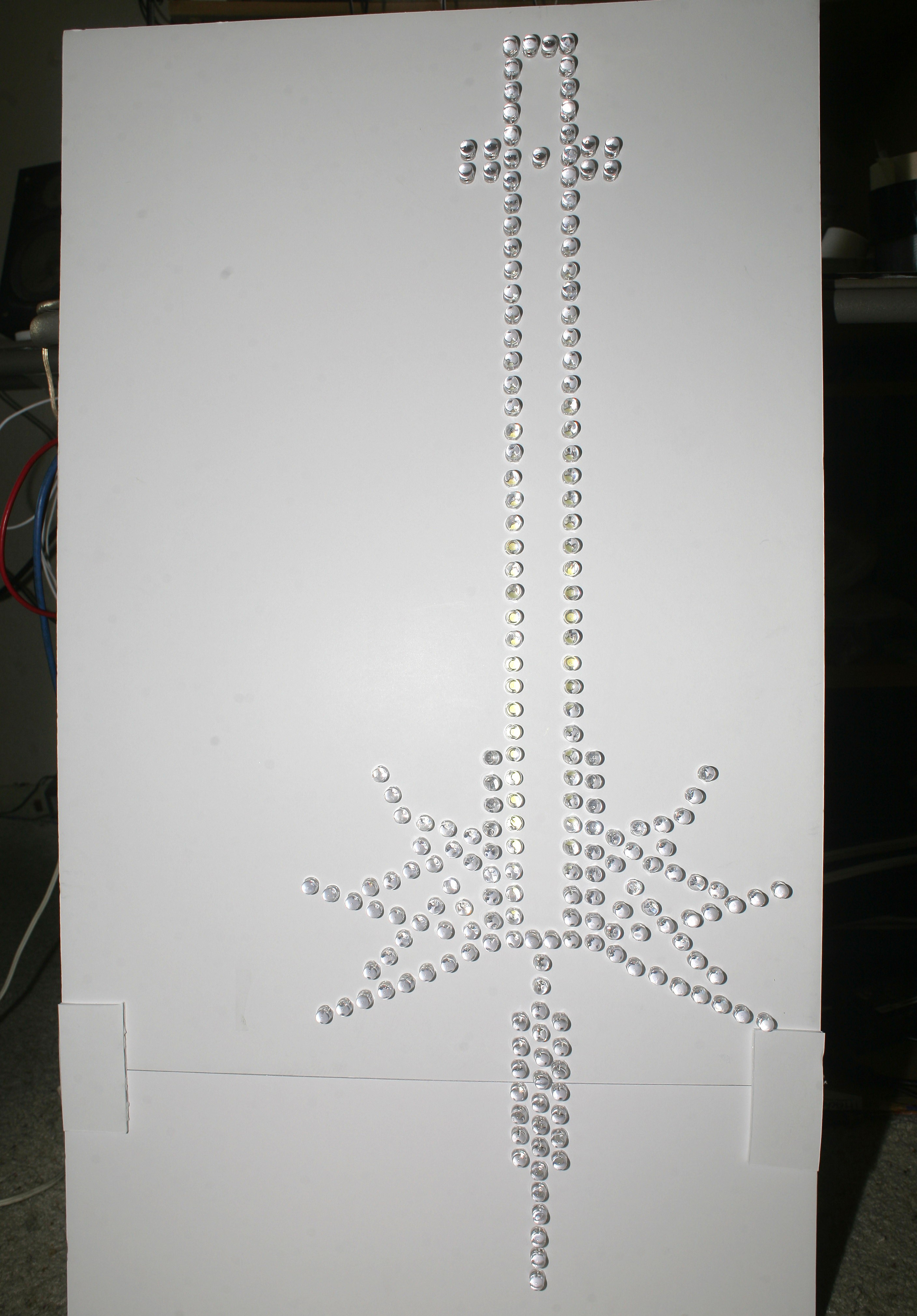
210 LEDs installed. 1 was bad.
The soldering was brutal. This part would be just as nasty with a microcontroller. Optimizing for the least current usage made it complicated. The lion kingdom already made a clock with all the LEDs in parallel & swore never to do it again.
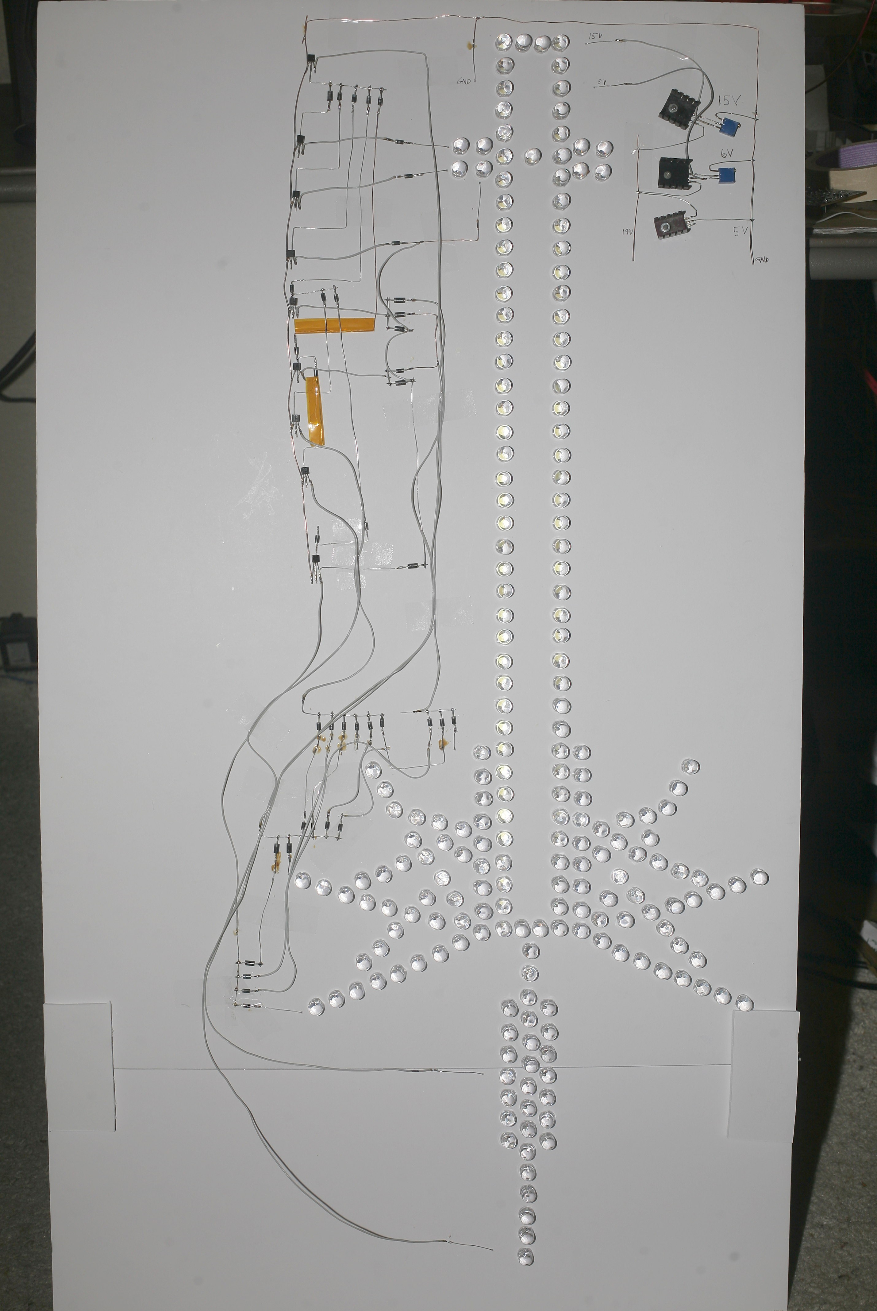
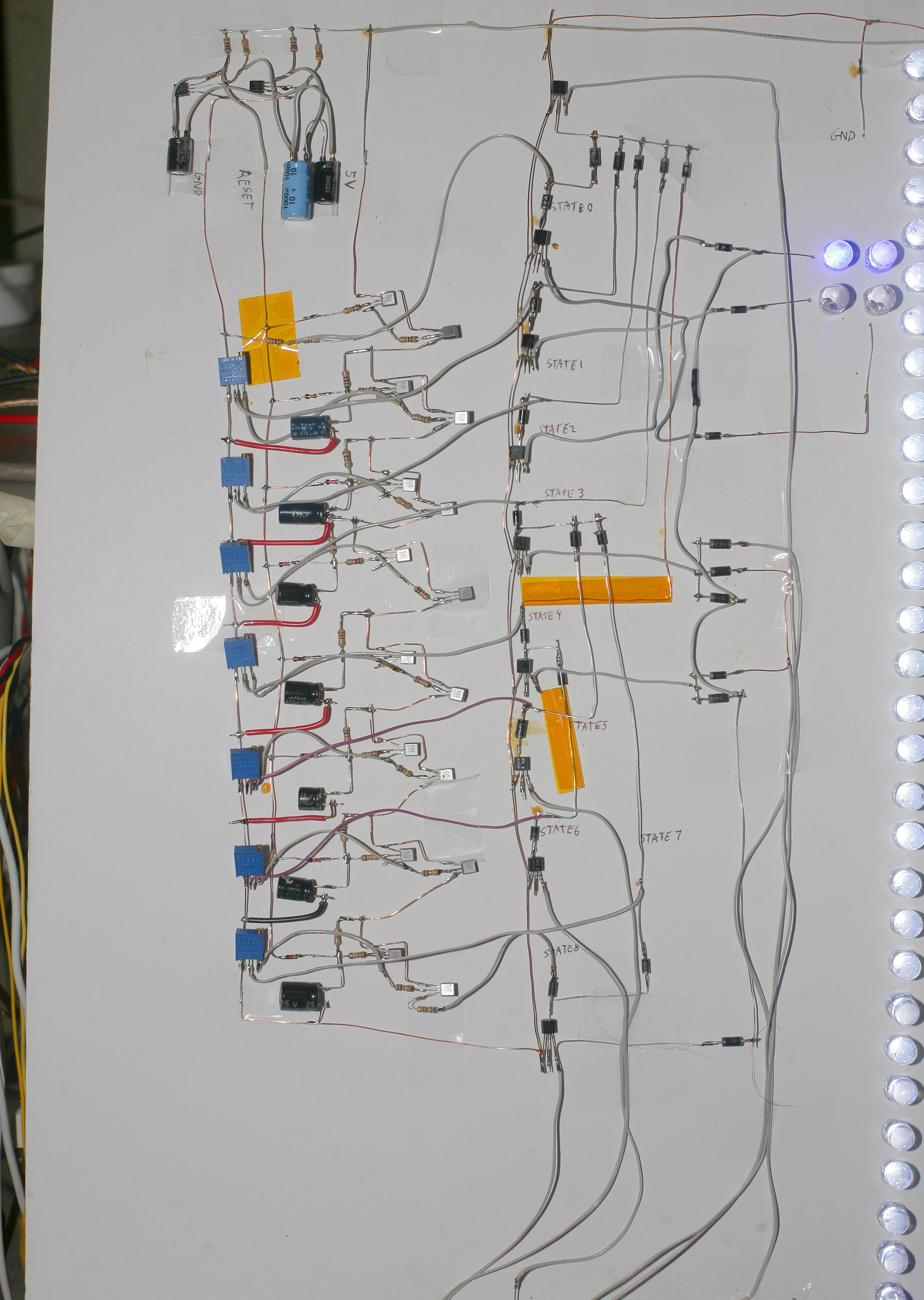
Diode logic installed based on a simplified design. The lion kingdom remembered the days when it could be home more than 4 hours.
Another 2 hours replacing diodes & resistors & the 9 states lit up. Shottky diodes can't be mixed with silicon diodes for it to work. All the transistor states needed a diode voltage drop before the base. The grid fin states were swapped. The white LEDs are too bright & might need a separate voltage regulator.
More voltage tweeking, diode replacement, & a 4th voltage regulator.
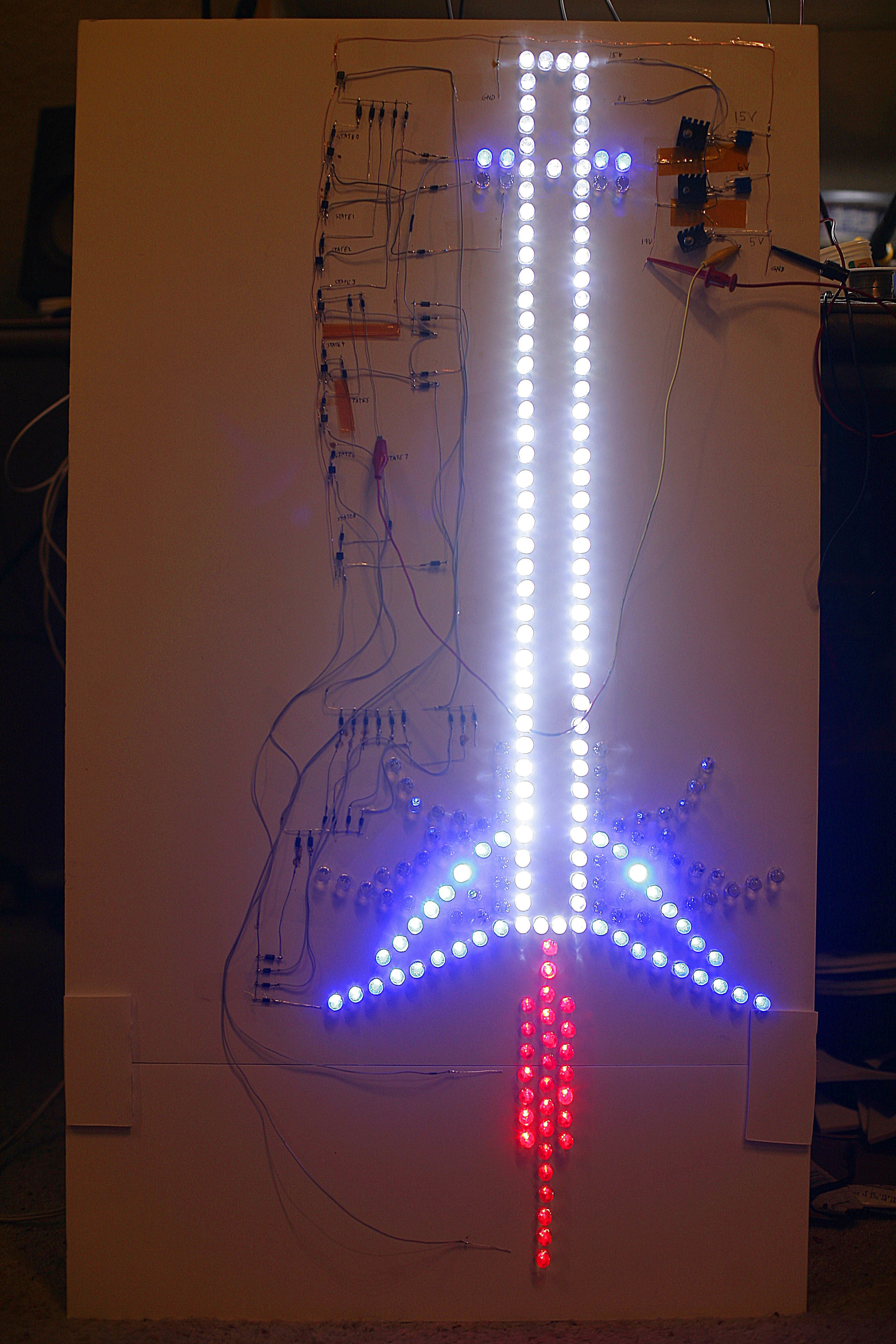
Finally, the sequencer was mated, the multivibrator was fabricated, & it started animating.
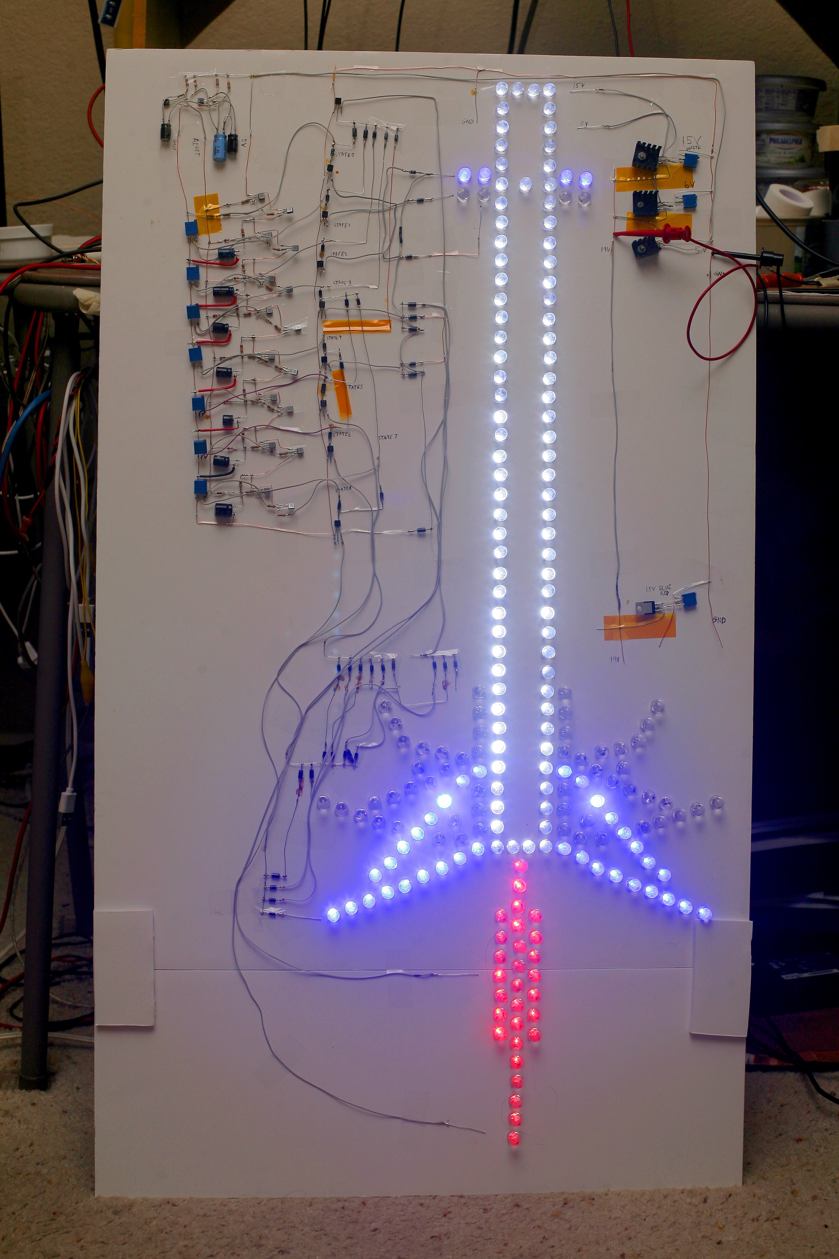
All the delays worked with the pots at 500R + 500R. There will be some tweeking to reduce the overlap & replacement with discrete resistors as pots are used in other projects. The multivibrator needed a 220uF & a 1330uF to generate the reset pulse at the right time. Accidentally plugged 19V into the 15V rail, but the power supply was current limited so it didn't burn out any LEDs. Saved again by a current limiting power supply set to the lowest possible value.
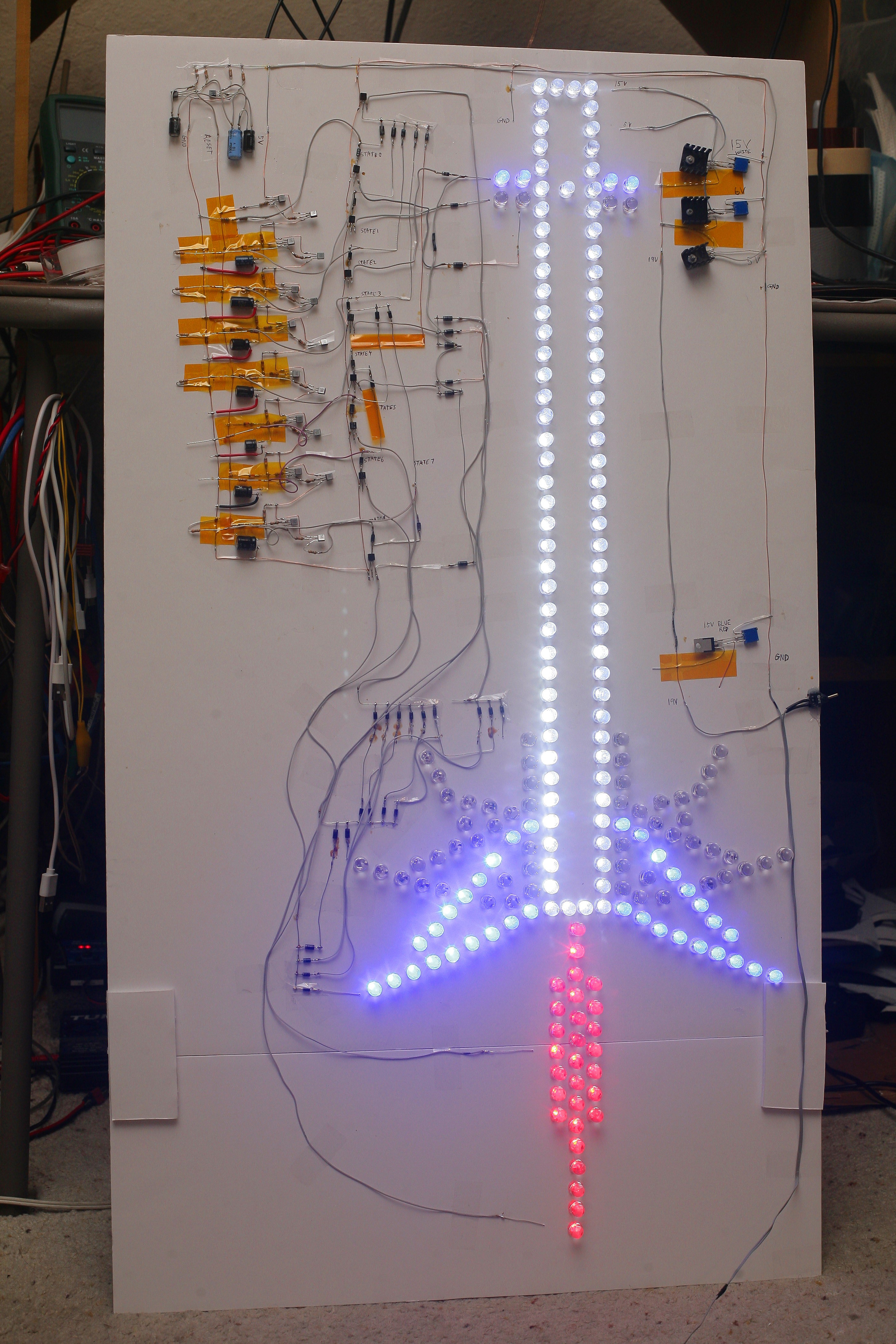
Replaced all the delay pots with fixed resistors to make the LEDs overlap less. 475 + 330 worked. 475 + 325 didn't work. That's well within the precision of the resistors. There was a lot of fudging of minutiae to make all the analog values work. This made the delays slightly shorter, which would entail adding capacitors to correct. Once the novelty of controlling animation with analog delay circuits wears off, the animation gets quite boring, so the lion kingdom called it quits.
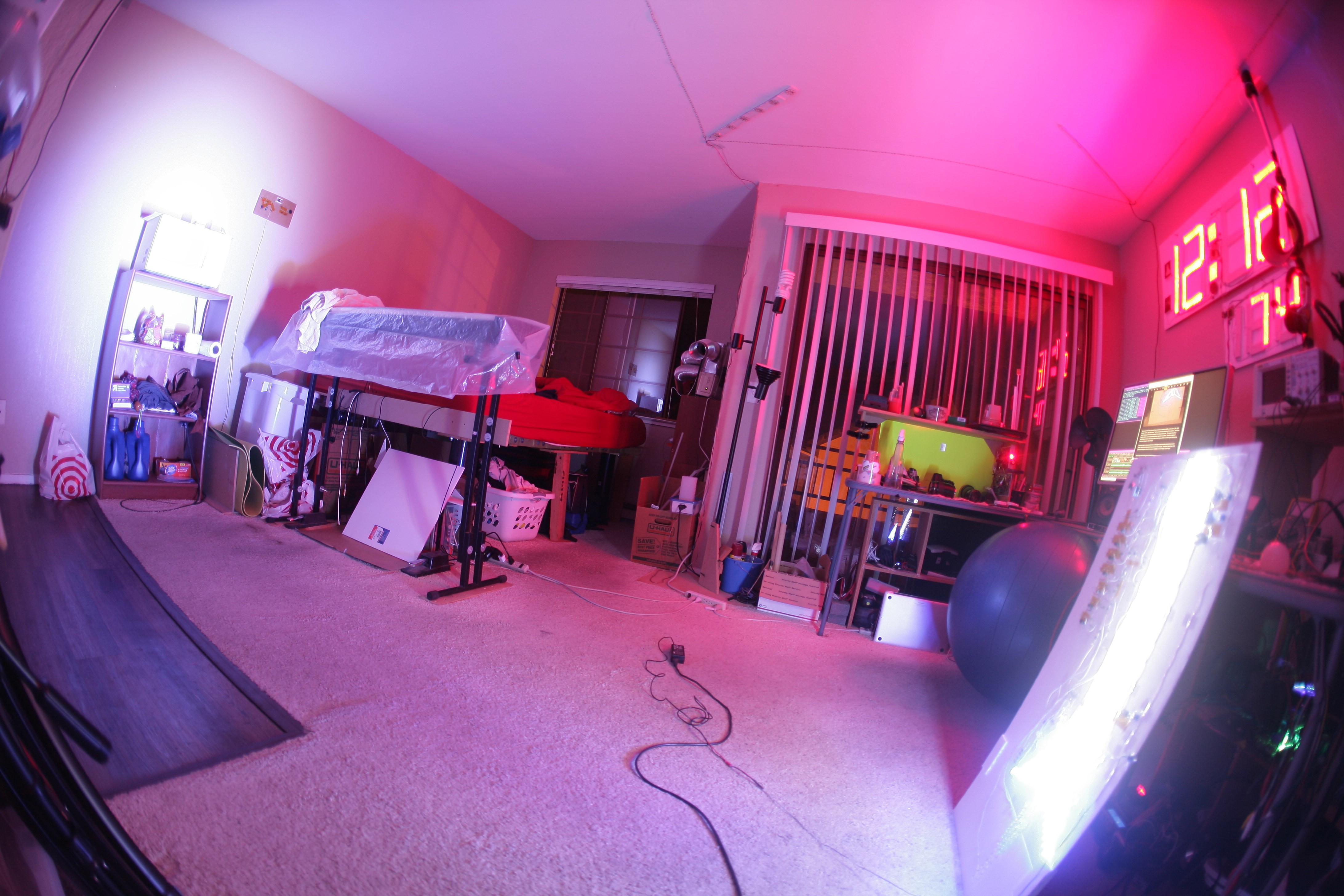
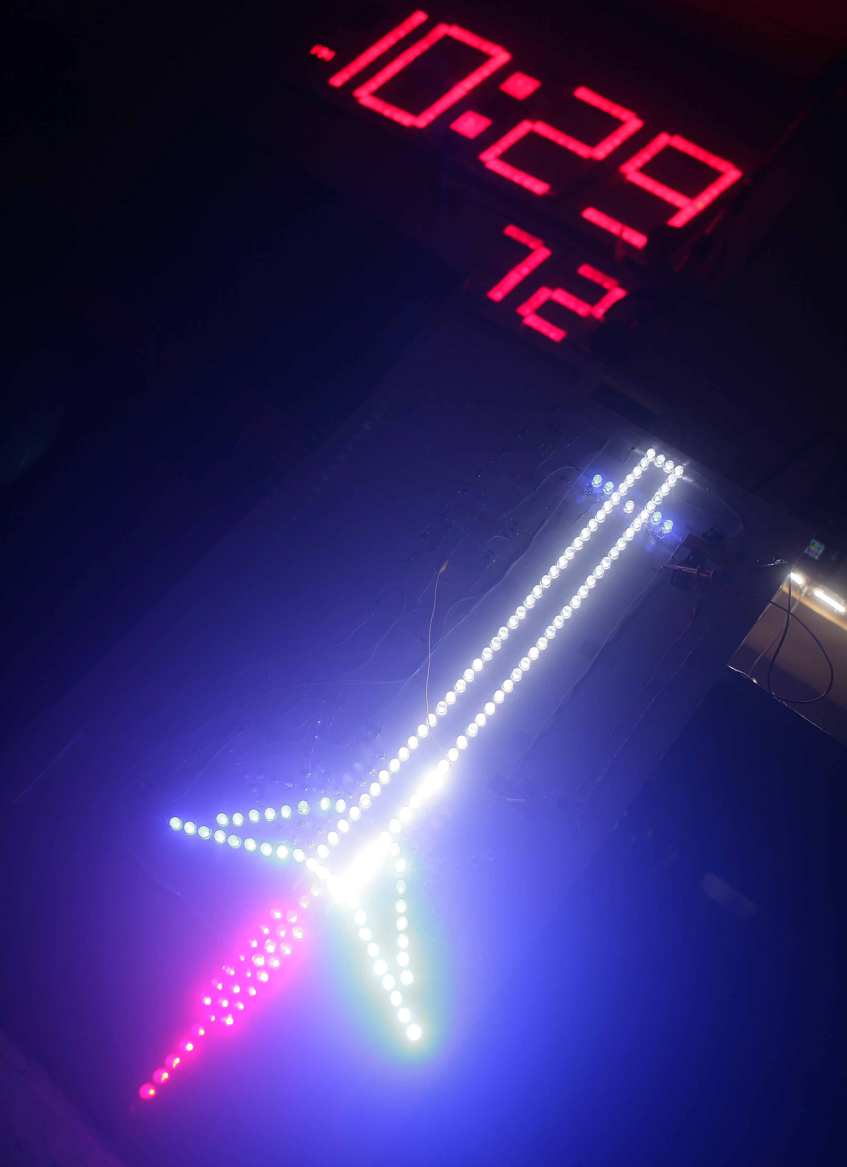
It was too bright to sleep by & the blue white light it cast was quite depressing, so put a power switch on & connected the permanent power supply. Lions have found blue white light depressing ever since the arrival of a daylight fluorescent light, 8 years ago. Perhaps it reminds them of an eternal twilight.
Wish it had more moving parts, but the lion kingdom accepted the moving parts occupy only a small part of the real rocket. A microcontroller could have eliminated most of the voltage regulators with PWM. Discrete analog is expensive.
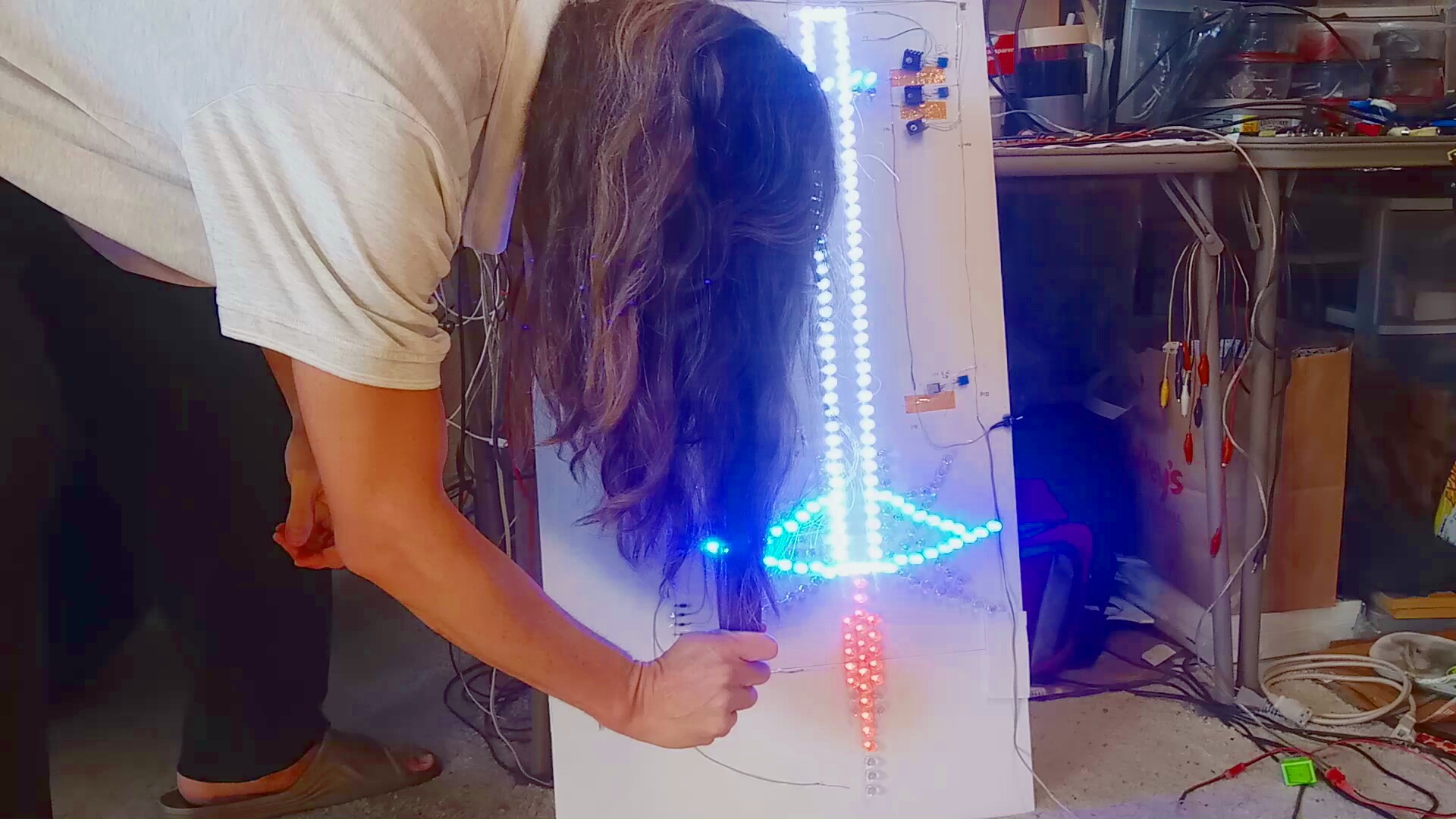
Size comparison with the mane.
After 2 years of flickering, uneven LEDs, & instant state changes, the pure BJT design finally succumbed to a modern 20 year old microcontroller. It just wasn't going to look good enough with 1970's parts, for any reasonable cost.
There's actually a simpler sequencing circuit for discrete transistors. It doesn't use a clock generator & each state only needs 1 transistor.