 lion mclionhead
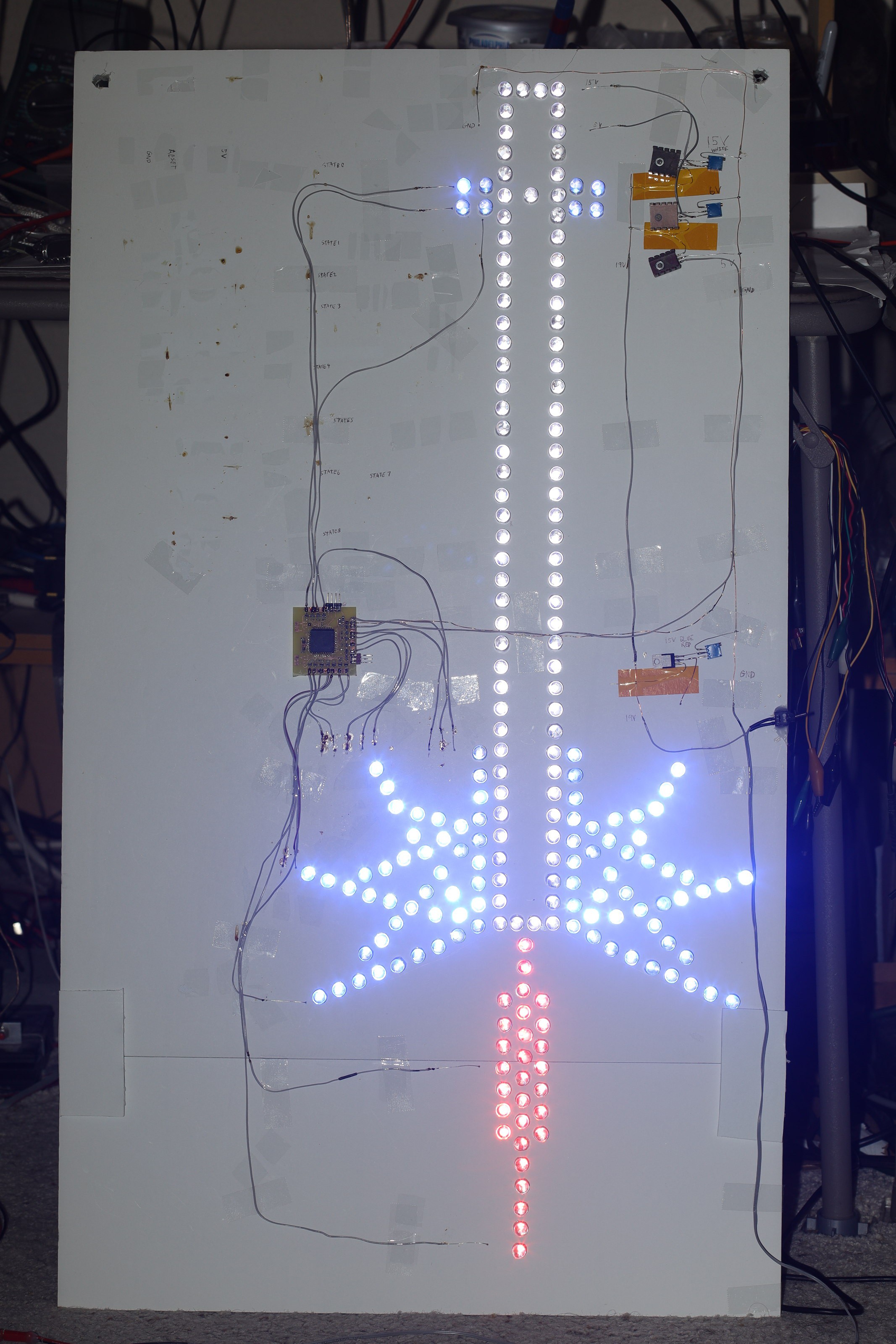
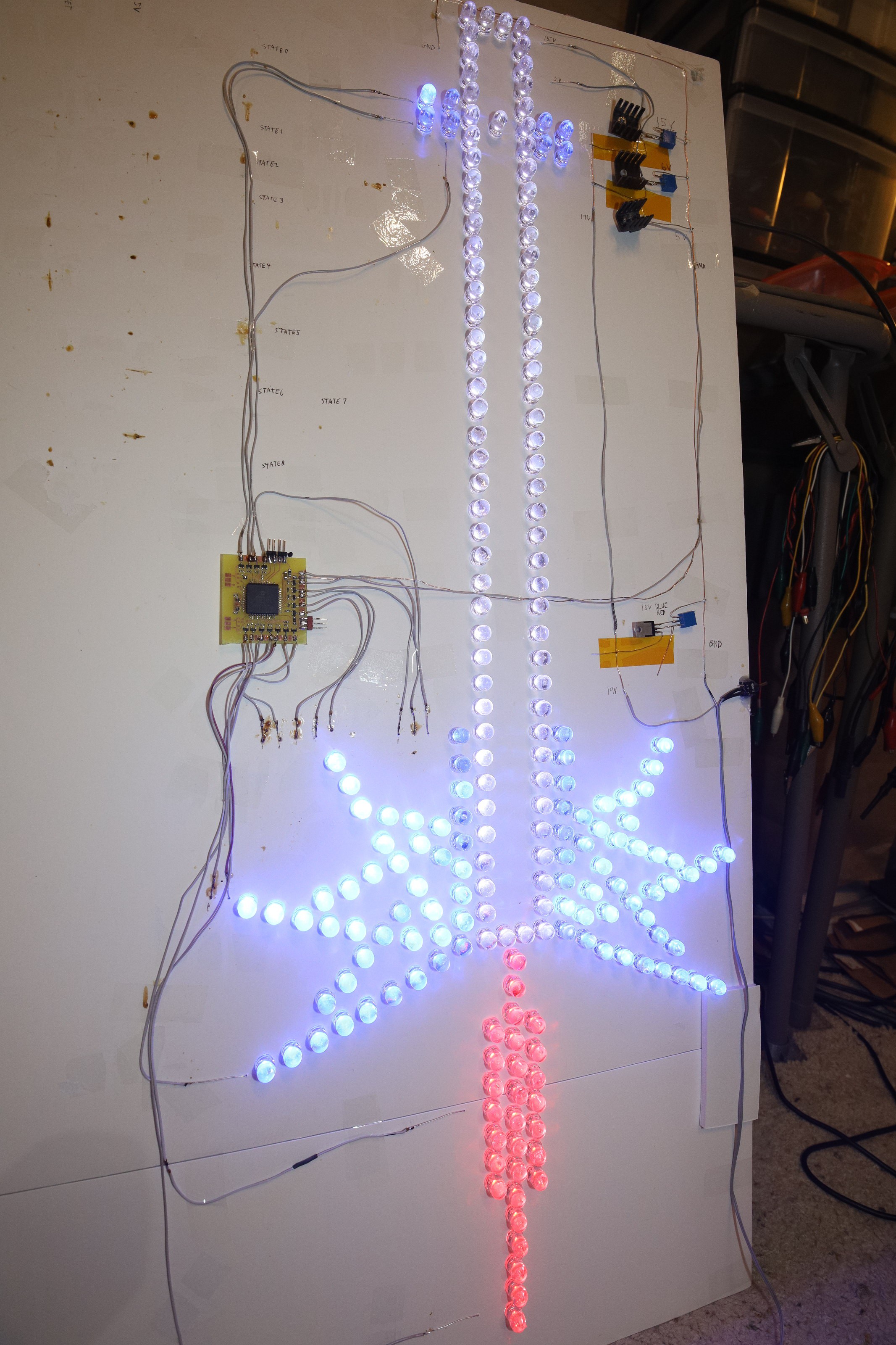
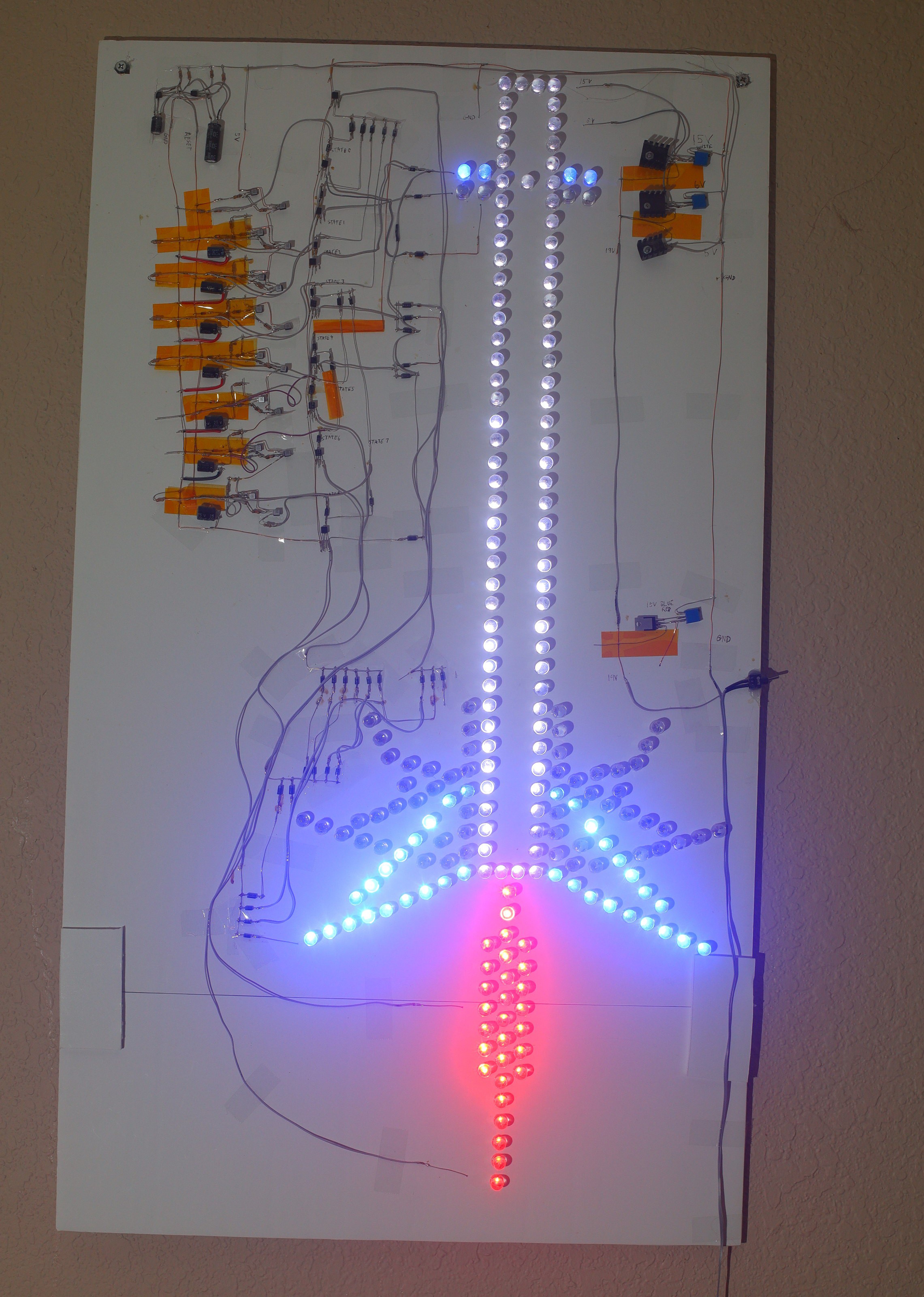
The lion kingdom was pondering how to extend the multivibrator into a more sophisticated display & it led to a 9 state animation with 5mm LED's placed side by side, the way lions envisioned such things 40 years ago. Microcontrollers would have been expensive. A fully equipped hobbyist would have done it with TTL logic, in those days.
Lions only knew about BJT's. Lions didn't know the values or how to connect them. What if the way lions envisioned doing it 40 years ago was actually possible?
The heart of the animation is a sequencer. A sequencer for 9 LED states can be made out of 7 delay circuits. It would take far less components than a shift register out of BJTs.
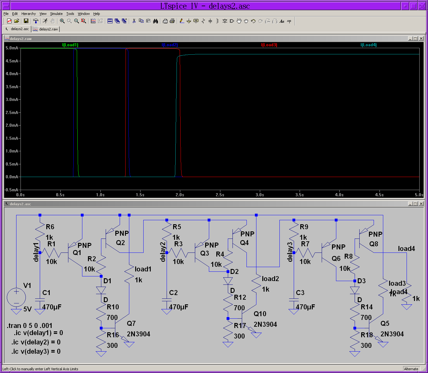
The 700/300 resistors & 2N3904's comprise the switches that turn on the LED strings. The loads are enabled though diodes so multiple states can turn on the same LED strings.
C1, R1, R6, Q1 is the delay circuit which turns on the load. A capacitor C1 slowly raises the base voltage of the load transistor Q1 until it shuts off. The capacitor asymptotically approaches the base cutoff voltage but never quite reaches it, so it needs R6 to pull the voltage up to the rails.
With the load diode D1 no longer receiving current from the delay transistor Q1, a tiny current from the base of Q2 is now drawn to feed the load & Q2 turns on to turn on the next delay module.
The load diode gets a big current from Q1 or a little current from Q2, but always gets some current. The idea that anything is turning off is only an illusion.
The load switch Q7 turns on the LED string when there's a big current & turns off the LED string when there's a little current. This selectivity is created by a 700/300 resistor divider. With little current, the 300 voltage is below the base voltage so the transistor turns off. With big current, the 300 voltage is above the base voltage so the transistor turns on.
The trick is the delay transistor Q1 starts turning off when the capacitor voltage hits 4.5V, then some time later the Q1 transistor completely turns off, the load switch Q7 hits 0.5V & turns off the LED string. The gap between the 2 transistors has to be narrowed by raising the cutoff voltage of the LED switch Q7 closer to 4.5V. The resistor divider raises the cutoff voltage by presenting 0.5V to the base when it receives 4.5V.
The resistor ratio depends on how much current the load switch needs to turn on, so it's a finicky tongue angle adjustment. The delay sequencer can't be tested without the loads. Such are the interdependencies of a minimal component, historic design.
After the last delay circuit has fired, we need a 0V reset pulse to ground all the capacitors & restart the sequencer. The 0V pulse comes from a multivibrator. With a 0V pulse, the final LED string doesn't need a delay since the reset pulse will stop it. Also with the 0V pulse, the 1st delay circuit doesn't need the capacitor C1 or the pullup R6. The reset pulse can turn on & off the delay transistor Q1 directly.
Since brightness wasn't a priority, all the LEDs could be obtaned from a cheap kit.
https://www.amazon.com/Emitting-Assortment-Diffused-Yellow-Colors/dp/B07DQQCXV9/
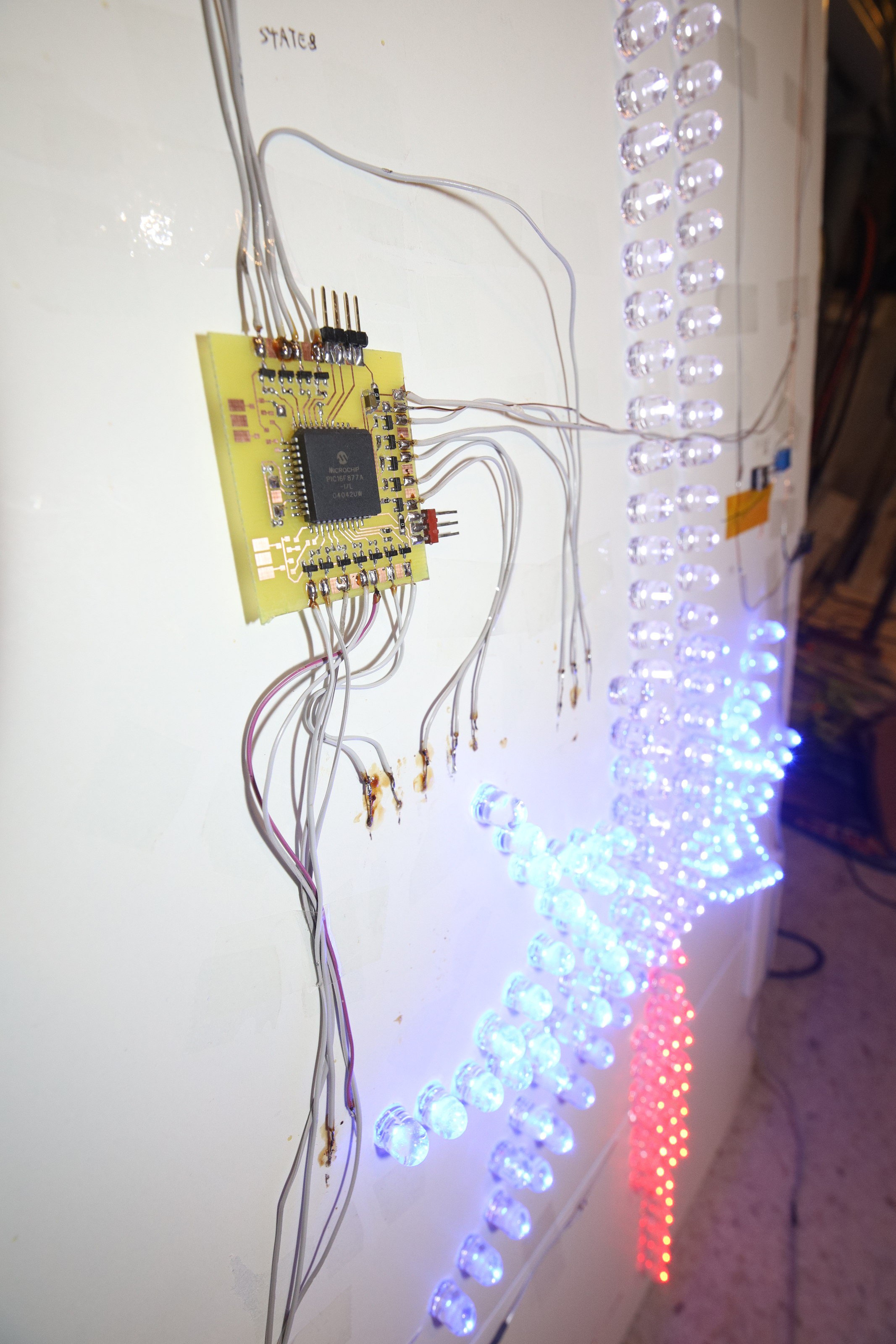
Of course, if you're going to spend months paw soldering 210 LEDs, they might as well be jumbo sized.
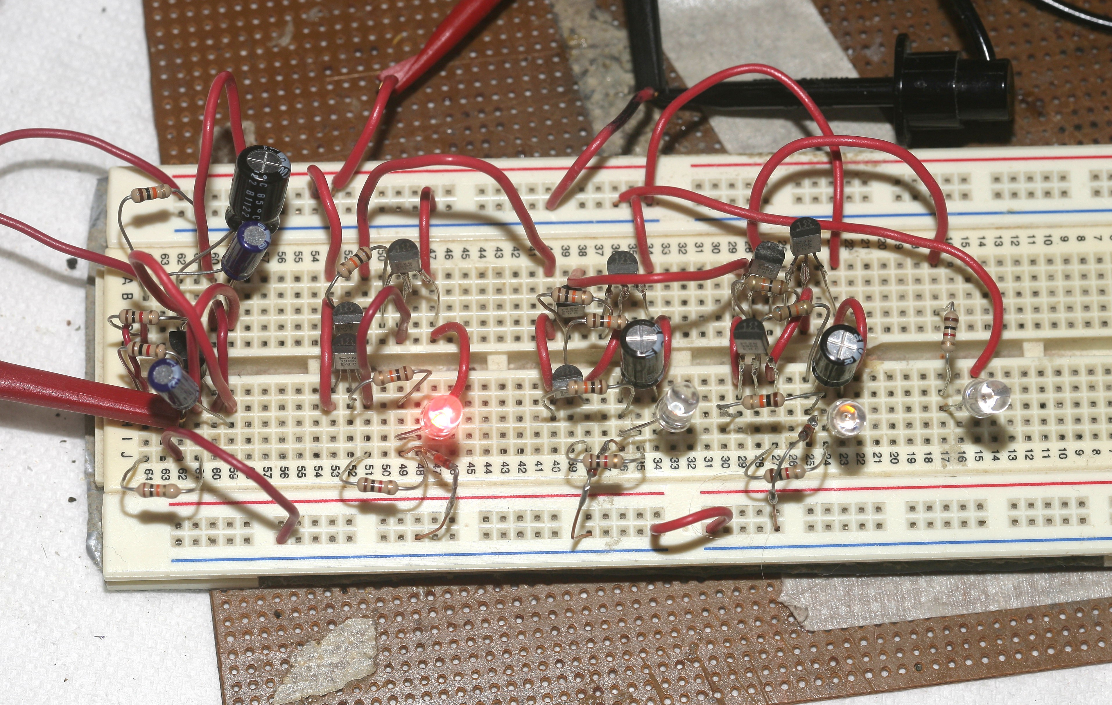
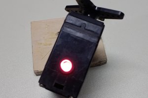
Early sequencer on a breadboard for checking delays.
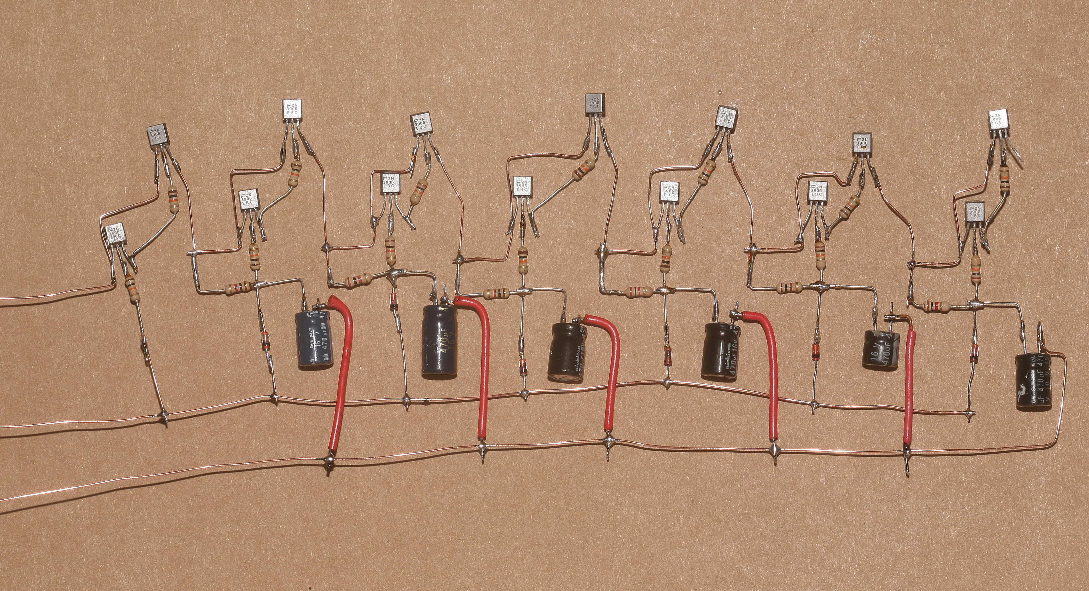
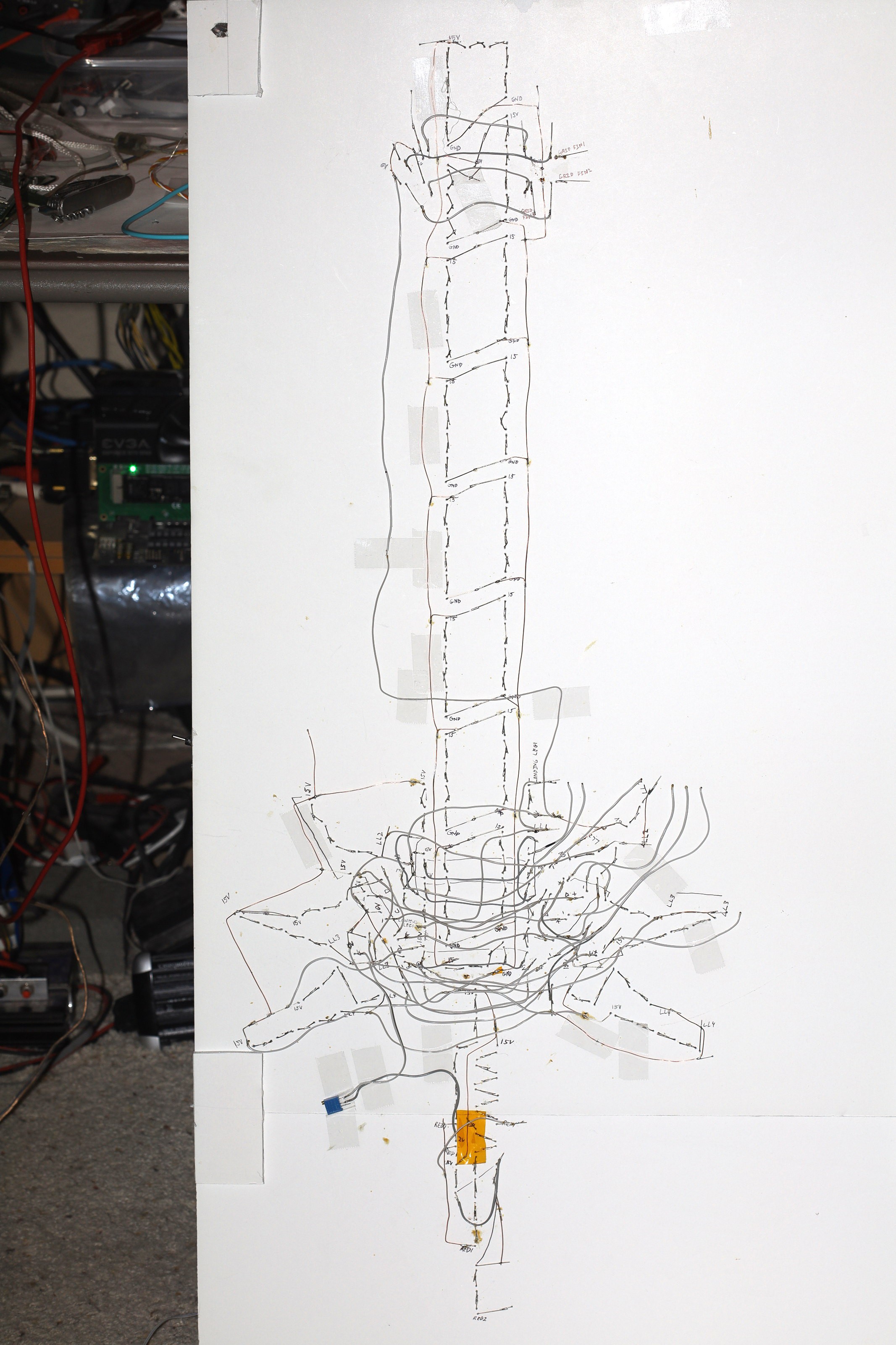
The sequencer was fabricobbled point to point, as it would have been done 40 years ago, to make a living schematic with all its wiring visible.
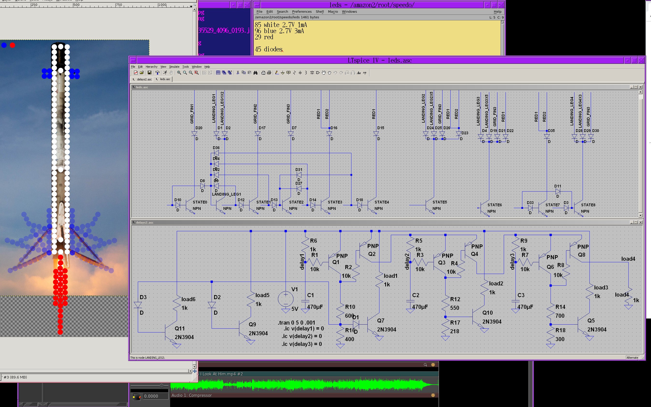
When it came time to translate the 9 sequencer states to the LED voltages, the insanity of trying to do it in analog began to escalate. The 1st problem is it would take hundreds of diodes to fabricate a memory device capable of switching on the right LEDs in the right states. This could be simplified down to 45 diodes by offloading...
Read more »

 Simon Merrett
 Glenn.Kubota (gee.k)
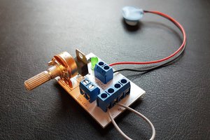
 Ted Yapo
I dig the IRL schematic. That's some cool planar circuit sculpture right there!