 A.M. Smith
Overview
Before the video thumbnail gets your hopes up - no, it does not work.
Swings pretty nice though. There is no motor action occurring here.
In this iteration, the pendulum is mounted away from obstructive surfaces through use of a right angle clamp and dowel.
Not yet programmed (but pictured) is a Teensy 4.0 with a familiar module - the MPU9250 Accelerometer/Gyroscope. The Teensy 4.0 boasts a 600 MHz controller, much beefier than the Arduino Nano (16MHz) used on Mk I.
Not pictured (and never to be) is an L298N motor driver for the BLDC motor. I've learned through a few posts on Hackaday not to be afraid of using more recent technologies to drive the motor, so for the next iteration I will be using the TB6612 or MAX14870 modules which are lighter, smaller, and more efficient than the L298.
I 3D printed a wheel of the desired radius, which I have attached to the motor until I can get a steel wheel fabricated/cut. With luck, the print will suffice in terms of mass.
Why not continue with the Mk II?
To power the electronics while the rig is spinning, I was counting on a fragile and hacky slip-ring substitute.
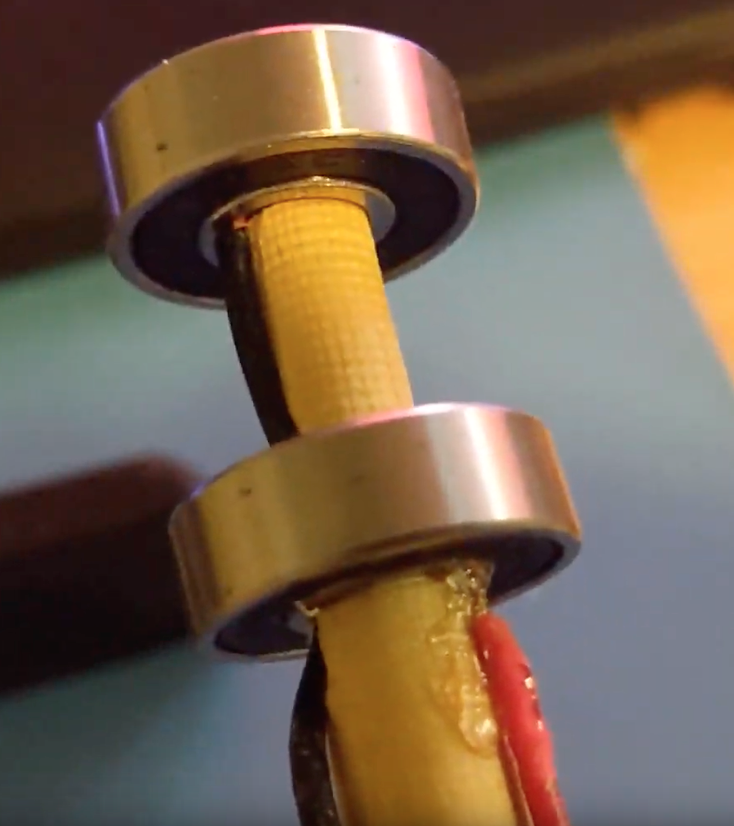
As pictured with the red wire, I squeezed a wire end between the wooden dowel and the inner wall of the bearing. The ball bearings separating the inner and outer walls are conductive (with these bearings but not with all bearings, I've found). Another wire squeezed between the outer wall and the PLA casing of the pendulum would complete the pathway. This would (theoretically) allow complete 360 degree rotation of the outer wall without breaks in electrical connection. I would put an LC circuit on the pendulum board to smooth out the supply.
The benefit to this kind of slip ring is that you can put solid axle directly through it. Traditional (cheap) slip rings don't have such a convenient hole through which to place a rotating rod (see Amazon product listed here).
However, I found no method of securing the wire to the bearing walls that withstood more than a gentle tug. As such, the play of the bearing and wire were enough to cause intermittent drops in power while the pendulum swung. I would likely need to spot weld wires onto the bearing walls for them to truly hold - I don't have such equipment.
Next Iteration
I will be purchasing a legitimate two wire slip ring and redesigning the pendulum and offset rod (clamped) to house it.
I have told myself this before, but never again will I use perfboard to prototype - I did it again for the Mk II and suffered for it just like every other time. I will lay out the PCB and have a few ordered this time.
Discussions
Become a Hackaday.io Member
Create an account to leave a comment. Already have an account? Log In.