The pin pitch on the SOT-23 packages is too fine for my homebrew PCB abilities so I had it fabbed by Oshpark. It was also a good practice for using Kicad instead of Eagle.
Glad I did since Captain Obvious made the mistake of trying to use the OPA197 as a comparator. I did so for reduced component mix and because comparators with wide voltage supply ranges have have long propagation delays - greater than 1uS. But as anyone who knows op-amps will tell you they cannot be used as high-speed comparators, no matter how fast they are (GBW). With a large voltage delta, the inputs saturate and take several microseconds to desaturate. I measured propagation delays greater than five - totally unusable.
I found two comparators that might work. Microchip has a pin-compatible open-collector, wide supply range comparator (MIC6270) that's cheap but slow - on the order of 600nS-1.3uS. But I could evaluate it in the existing prototype circuit. TI has a push-pull (TLV1805) that costs the same as the OPA197 and is much faster - 400-600nS - but isn't pin compatible.
For both, the approach is to set a lower Vref to commence turn-off at a lower current which, when accounting for their propagation times over temperature, terminates the duty cycle appropriately. This works for normal operation but won't protect against dead shorts. However, this is an acceptable trade-off since the circuit will be fused and a short means something is broken anyway.
I was able to evaluate the MIC6270 immediately with just the addition of a pull-up resistor to the existing PCB. I did a new layout for the TI chip that's a bit more compact (and hopefully transferable to a complete design). I'm already leaning towards the TI comparator since it's faster and has a push-pull output stage that eliminates the resistor. I'll post a log when that evaluation is done.
Here's the circuit that the OPA197 & MIC6270 were evaluated in.
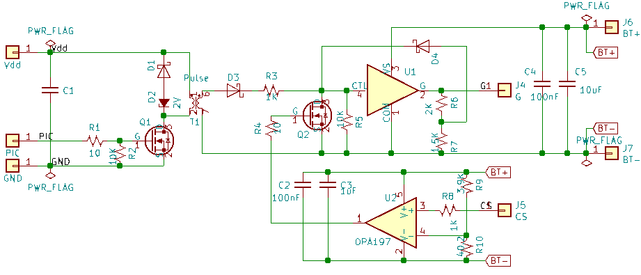
They were fitted to the flyback prototype and replaced the conventional gate drive circuit. A 1uS drive pulse is issued by the PIC.
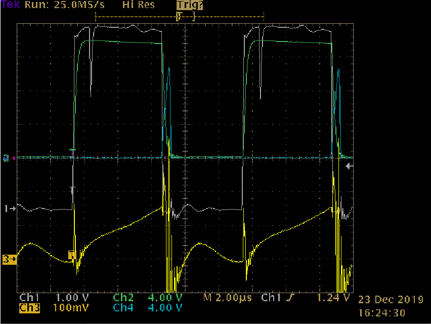
It did a bit better than expected. This trace was taken with a 14V supply emulating the battery. CH1 is the drive pulse seen by the gate driver's input, CH2 is the gate drive output, CH3 is the MOSFET source pin (e.g. current ramp), and CH4 is the comparator's output. At 14V the comparator should trigger at 140mV. There's about 800nS of delay.
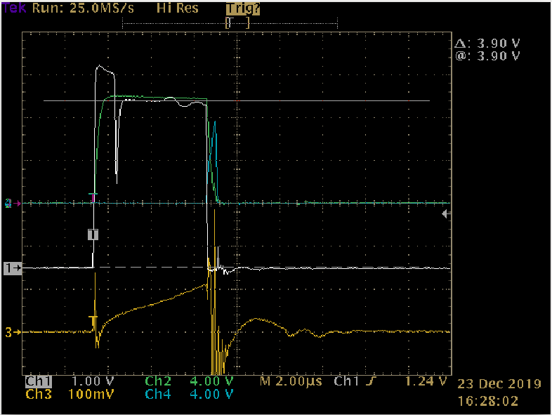
Here's the same trace setup at 10.2V. Identical timing (ratiometric) as intended. Note the drop in the positive feedback as well as the droop at the end of the drive pulse. Below this voltage the driver would fail to latch because the voltage divider (R6/7) minus D4's forward voltage was less than the pulse drive input. The droop is due to the feedback loop's relatively high impedance. So a refinement is to select divider values that ensure latching across the intended operating voltage with sufficient noise margin. The bottom of the divider could be eliminated but the higher voltage adds time to the turn-off.
I spent some time characterizing at various voltages, running in sampling mode (10kHz) as well as charge transfer (100kHz) and its operation is stable. Voltage measurements are consistent with those taken using the standard gate drive. In a pinch this circuit would work but I'm betting the TI will do better.
Last, the gate driver and MOSFET are not matched; the MOSFET's gate charge is considerable since it's designed to switch 100A and I had to use a 10 ohm gate resistor to limit peak current for the driver. Not surprisingly, the gate driver's output trace (CH2) shows a rounded turn-on/off and there is considerable ring with more dissipation from the MOSFET than expected. Not a big deal since wasn't the focus of validation.
Discussions
Become a Hackaday.io Member
Create an account to leave a comment. Already have an account? Log In.