Close
0%
0%

Power efficient motor driver

The project presented is a stepper motor/motor driver circuit board with SN754410 motor driver IC including some power saving features.

Public Chat
Similar projects worth following
224 views
It is built around SN754410 IC and a power switching circuit, it needs an external signal from controller to turn ON the power to the driver circuit. Using the switching circuit, the power consumption of the motor driver circuit is nothing until HIGH pulse is applied.

The project presented is a stepper motor/motor driver circuit board with SN754410 motor driver IC including some power saving features. The board can drive 2 DC motors or a stepper motor with the help of dual H bridge circuit in the IC. SN754410 IC is being widely used for driving motors as it operates in wide range of voltage and can drive up to 1A current per channel.

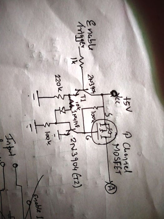
The additional thing here is the power switching circuit which will cut off the power to IC, this can be very power efficient than normal sleep modes. It needs an external signal from controller to turn ON the power to the driver circuit. The switching circuit is built around a couple of NPN transistors and a P channel MOSFET which will let the power flow only when we apply pulse to the circuit.

Using the switching circuit, the power consumption of the motor driver circuit is nothing and by applying a HIGH pulse to the switching circuit, one could easily use this board normally. Moreover, the IC is also capable of driving other loads such as relays or solenoids. Thus, with the additional power switching circuit, the board can become a very handy tool for makers.

  • Power switching circuit

    Patel Darshil12/08/2019 at 10:53 0 comments

    The power switching circuit cuts off the power to the IC until it gets a high signal externally. For example, when using this circuit in a project like a PIR motion detector with Arduino, it will power Arduino when something is detected by the sensor and technically saying when the sensor sends a HIGH pulse. Here we are using this circuit in our motor driver board which will not let the power flow to the IC until a HIGH pulse is applied at the trigger pin externally saving majority of the energy while the driver is not needed.

    The circuit is built around a P channel MOSFET and a couple of NPN transistors. When a HIGH pulse is applied to the circuit, transistor T1 becomes active and there is power reaching the base of transistor T2. So Gate pin of the MOSFET is pulled low and this allows the current to flow through the MOSFET and the board gets power.

View project log

Enjoy this project?

Share

Discussions

Similar Projects

Does this project spark your interest?

Become a member to follow this project and never miss any updates