 Michael Gardi
With the Input, Output, and Core Panels done it was time to tackle something a little more challenging, the ALU. Since I had a small stash of signal relays burning a hole in the bottom of my parts bin (graciously donated to my makerspace Kwartzlab Makerspace), that was the implementing technology of choice.
As an aside, about the time that "How to Build a Working Digital Computer" was published, I was making simple relay based "computers" (like a tic-tac-toe machine for example). We had a family friend that worked for Bell (the local telephone exchange not the Labs), and as a result I had access to literally miles of 22 AWG solid core copper wire (unlikely to happen today). I made my own hand wound relays with bolts, nuts, washers, L-brackets, and tin strips cut from cans for contacts (so many scapes and cuts). Fun times.
At any rate I don't think I had occasion to use relays again until I built my Minivac 601 Replica, and of course now. When I did a search for "Relay ALU" I was astonished how much work has been done in this area, hundreds if not thousands of man hours of effort. I looked at ideas from the pioneering work of Konrad Zuse to more recent contributions by roehl and others right here on Hackaday.io. At the end of the day I came to the same conclusion that Dylan Brophy did and chose this 1-bit Relay ALU designed by Dieter Mueller:

Such a cool design. It was a good fit for the DPDT and SPDT relays (with polarized coils) that I had on hand and provides a lot of functionality for the part count (overkill for this project actually). Truly standing on the shoulders of giants here folks.
So after a successful breadboard test:

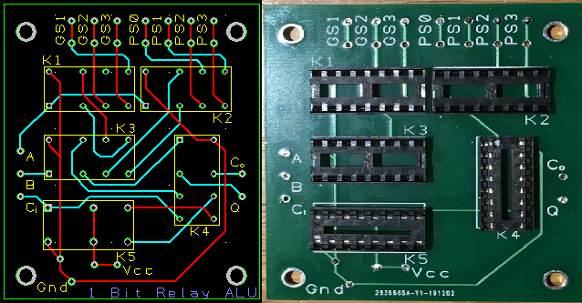
I designed and tested a 1-bit ALU PCB.
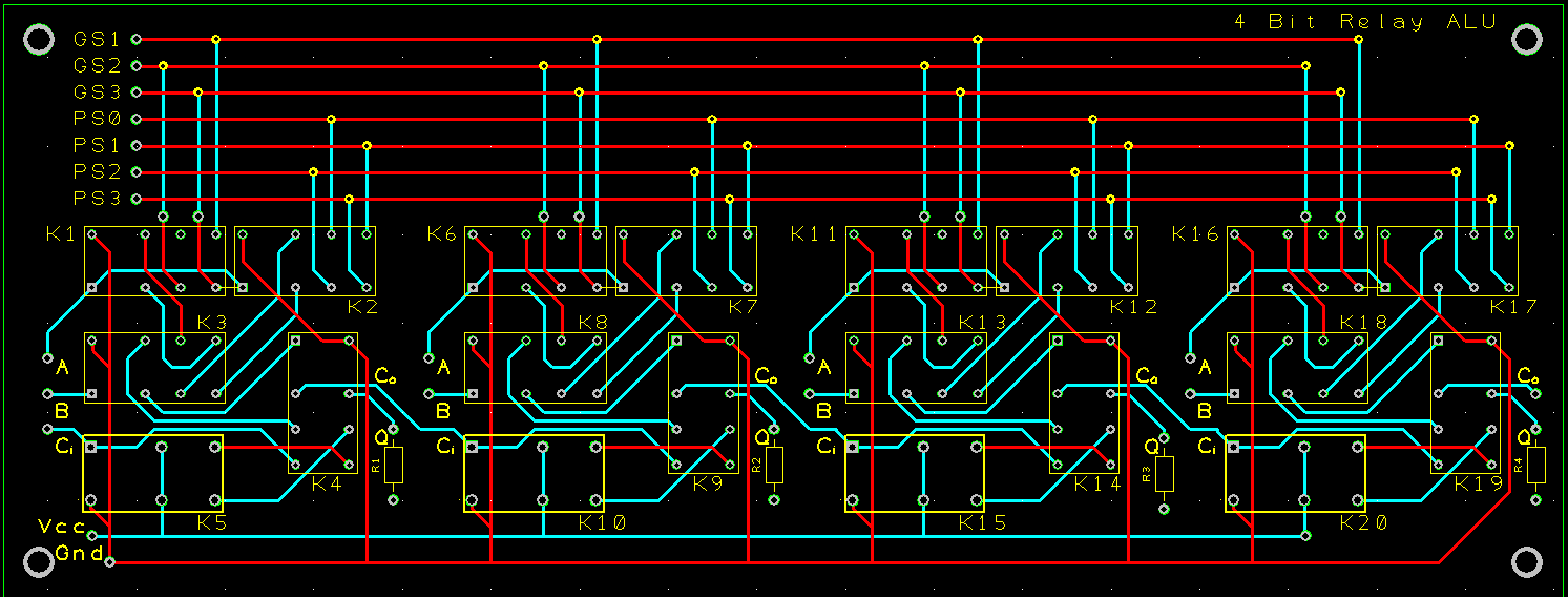
My initial thought was to stack 4 of these but at the end of the day I decided on a 4-bit ALU PCB to minimize the wiring:
The actual board was from the same batch where Top Documentation text was not silkscreened on:
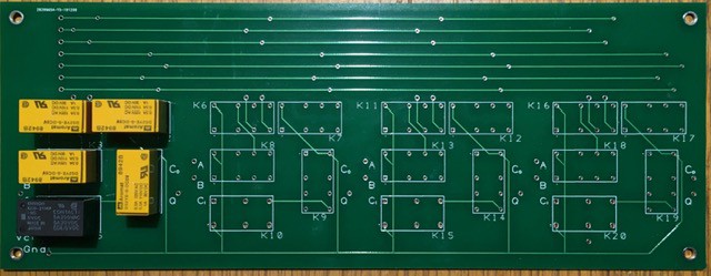
Also limiting resistors have been added to the design after this board was produced. As you can see, as of this writing, I've just started populating this board.
This ALU is of a multiplexer design with the operation to be performed controlled by the 7 inputs GS1-3 and PS0-3. So from Dieter's site here are some examples for configuring the multiplexers to work as Logic Units:
  GS   PS
 3210 3210
 ~~~~ ~~~~
 0000.1010 Q=A             DISPLAY A
 0000.0101 Q=/A            INVERT A
 0000.1110 Q=A|B           A OR  B
 0000.1000 Q=A&B           A AND B
 0000.0110 Q=A^B           A XOR B
 1000.0110 Q=A+B           A ADD B
 0010.1001 Q=A+/B=A-B      A SUB B
With that kind of capability I could not resist extending the ADD and SUB operations that the WDC-1 ALU needs to perform with the following optional operations:
- DISPLAY
- AND
- ORA
- XOR
- INV
- NOP
To select between these 8 options I'll need another Encoder. With a few tweaks to my Decimal to Binary Encoder design I created a 1 to 7 Encoder for the ALU:
Pretty much ready to assemble the ALU.
Discussions
Become a Hackaday.io Member
Create an account to leave a comment. Already have an account? Log In.