 Bharbour
Here is a little bit of historical information to show how the rest of the radio control system fits with the servo signals. Modern 2.4GHz radios transmit the servo control information as numerical data, as opposed to the older systems that used Pulse Width Modulation to convey the servo position commands. This is an explanation of the operation of the older PWM system operation.
Scope shots in the body of the article show two channels out of the data stream sent between the transmitter and the receiver. Here is a little bit more detail on the data between the transmitter and the receiver. It was captured from the trainer port on a 6 channel JR transmitter.
All of the information to be transmitted is available from the trainer port on an RC transmitter. The trainer port is used to allow a dual control setup for teaching people to fly RC. In use, the instructor holds the transmitter that is transmitting the data to the airplane. A cable connects the student transmitter to the instructor transmitter via the trainer ports. RF output on the student transmitter is turned off. A button on the instructor transmitter selects whether the control information from the instructor transmitter or the student transmitter get sent to the airplane. In any event, the trainer port is a convenient place to see the data out of an RC transmitter.
Each "frame" of data contains all of the control information for one instant in time. Multiple frames of data from a 6 channel RC transmitter can be seen in the scope shot below.
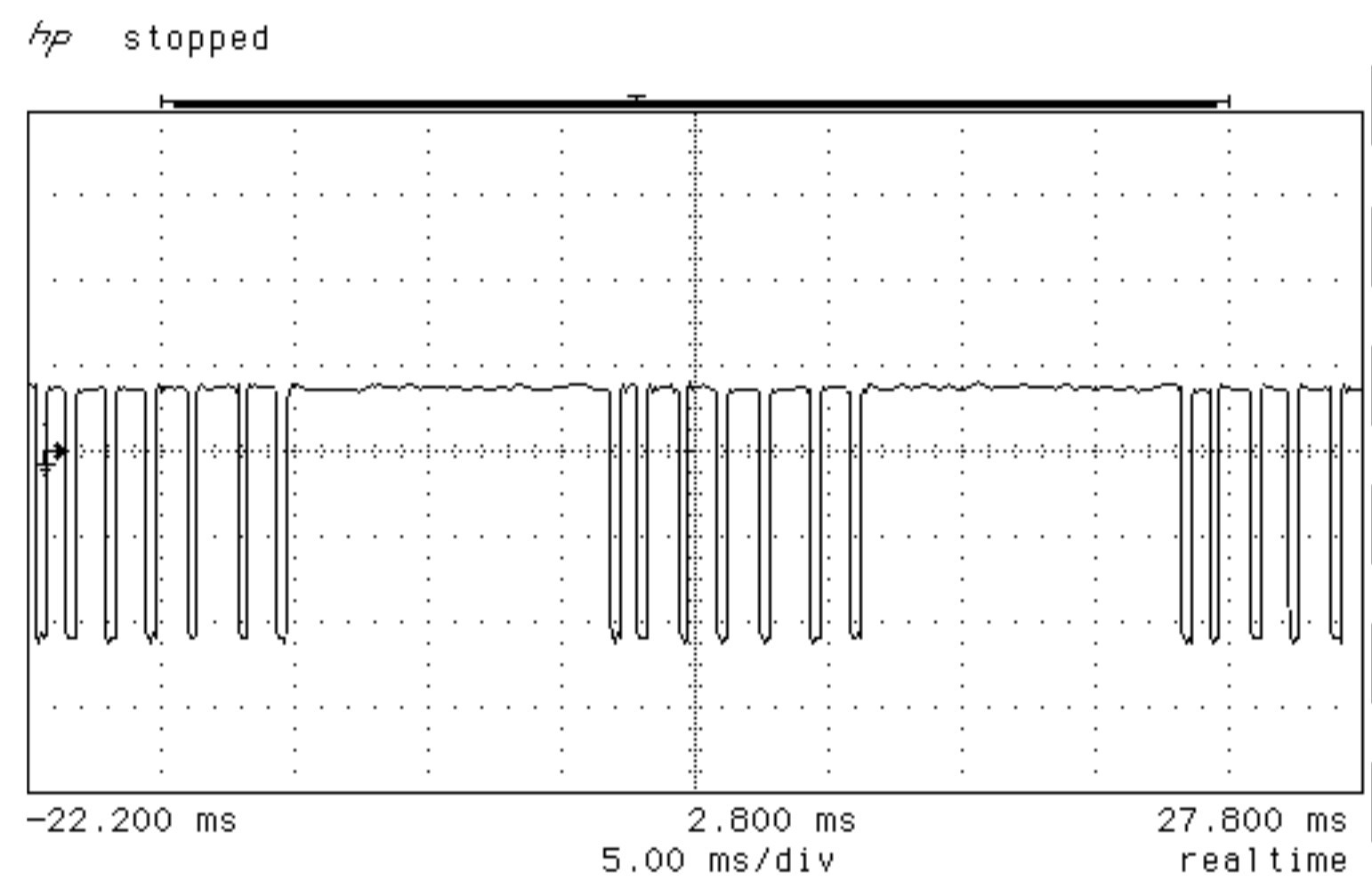
Looking at the group of pulses in the center, all of the control inputs are centered except the throttle and the Aux1. Pulse width is measured from falling edge to falling edge. The two longer "high" periods between frames (about 12mS each) are the frame synchronization periods, used to keep the receiver's frame decoding synchronized with the transmitter's frame encoding.
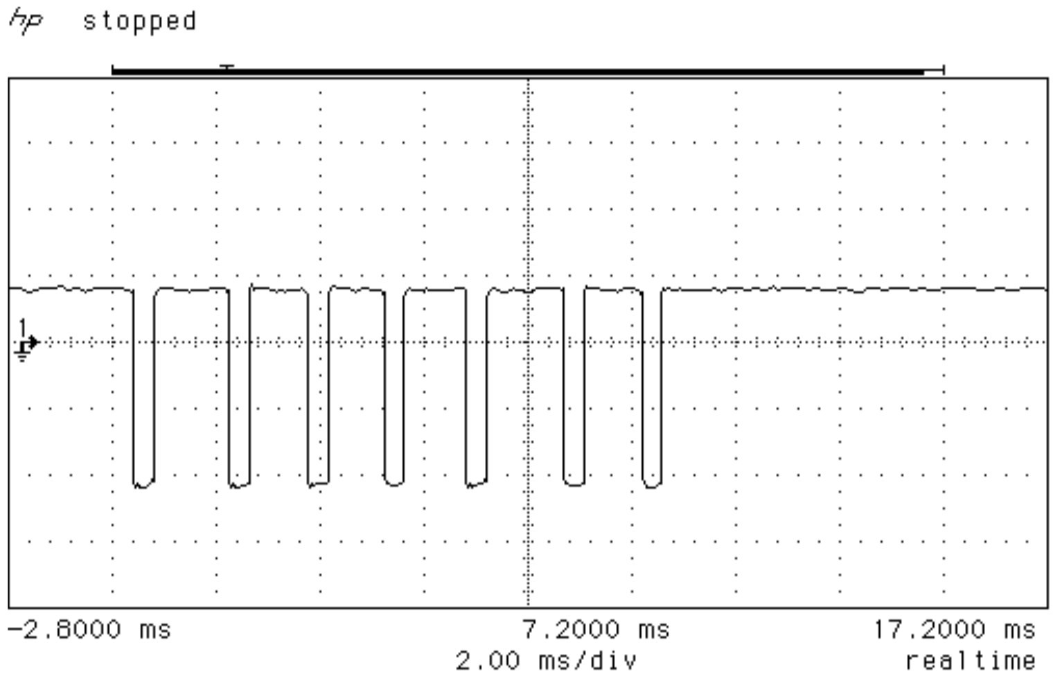
An expanded view of one data frame can be seen below. In this scope shot, the first pulse (throttle position) is set to the minimum value.

The next 3 channels are in their center positions. The width on the throttle pulse is about 1mS, while the next three pulses (aileron, elevator and rudder) are about 1.5mS. The fifth pulse (Aux1) is about 1.8mS, and the sixth pulse (Aux2) is about 1.5mS.
The next scope shot shows the results of setting the throttle stick to the maximum value.
Width on the throttle (first) pulse is now about 2mS.
Early transmitters were analog with discrete components in the encoder section. Analog transmitters allowed very little configuration of the relation ship between the physical controls and the output pulse lengths. With the arrival of computer controlled transmitters, the pulse width ranges can be changed to adjust the servo travel and the relationship between the physical control and the pulse width can be reversed to reverse the servo operation. Further flexibility like mixing channels and other things are possible.
Channel sequence tended to be consistent across a manufacturers product so that the trainer ports would work. There is no consistency in the sequence between manufacturers. The pulse width range and polarity is consistent with positive going pulses and 1mS to 2mS range.
Discussions
Become a Hackaday.io Member
Create an account to leave a comment. Already have an account? Log In.