0%
0%
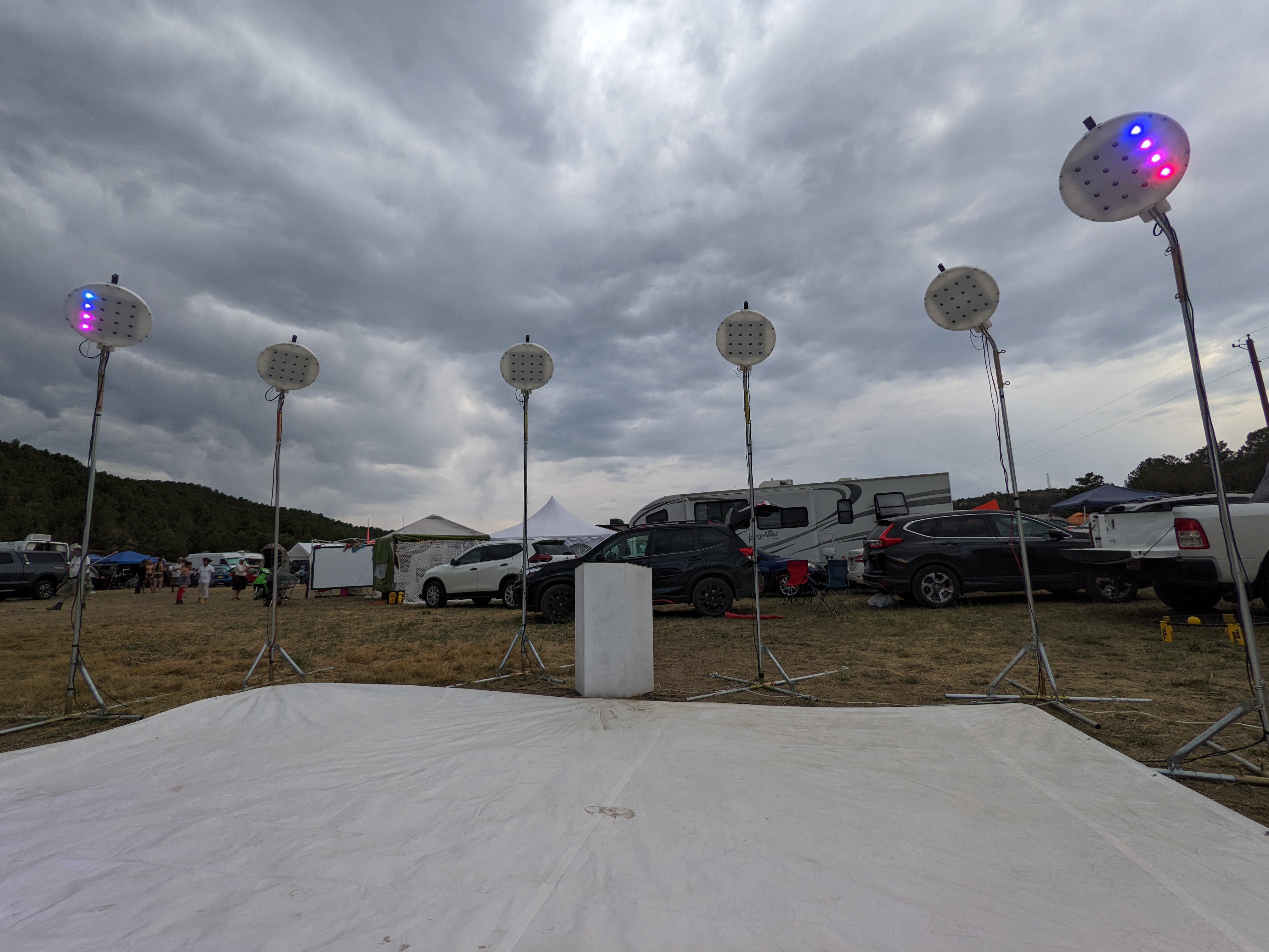
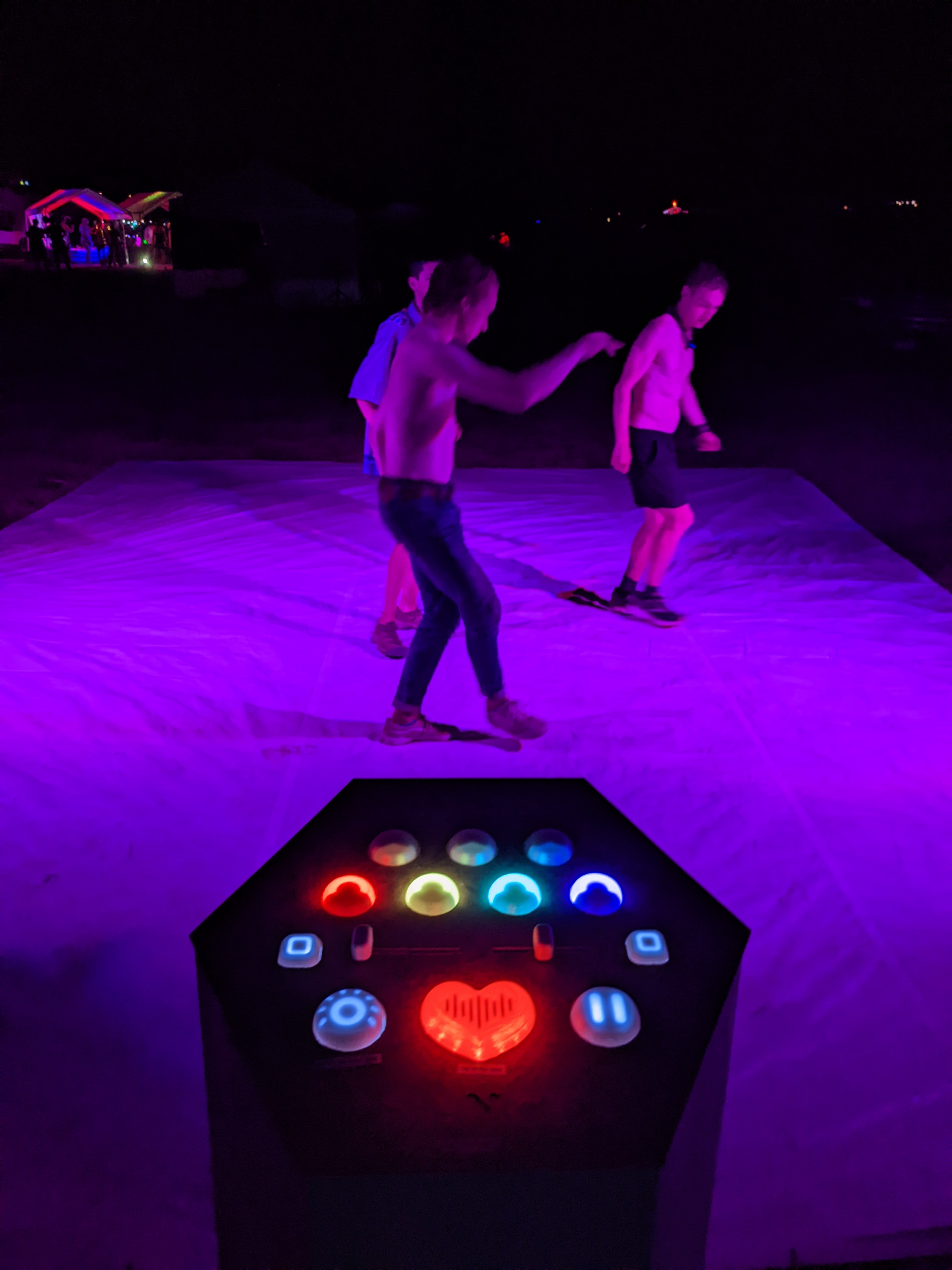
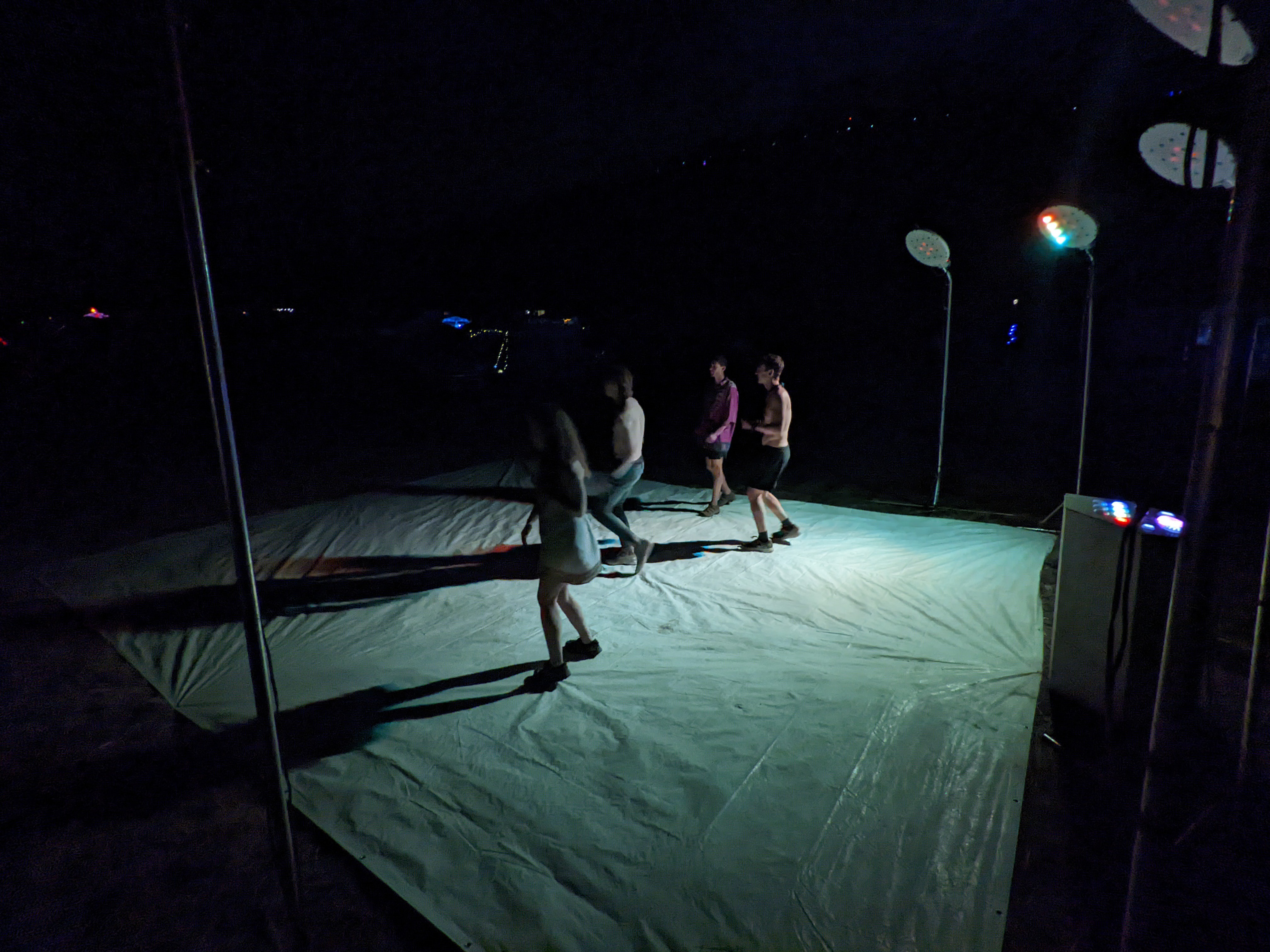
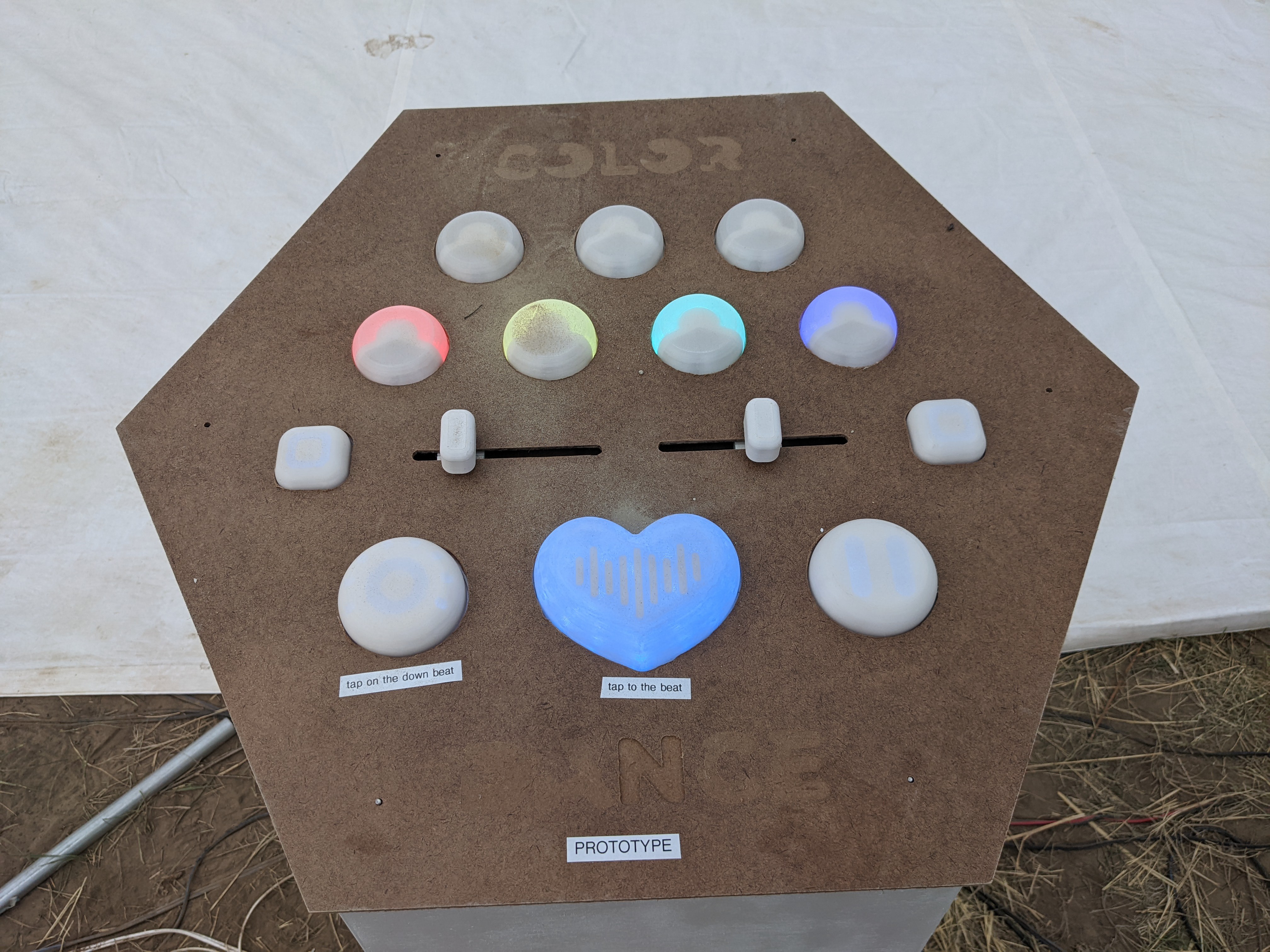
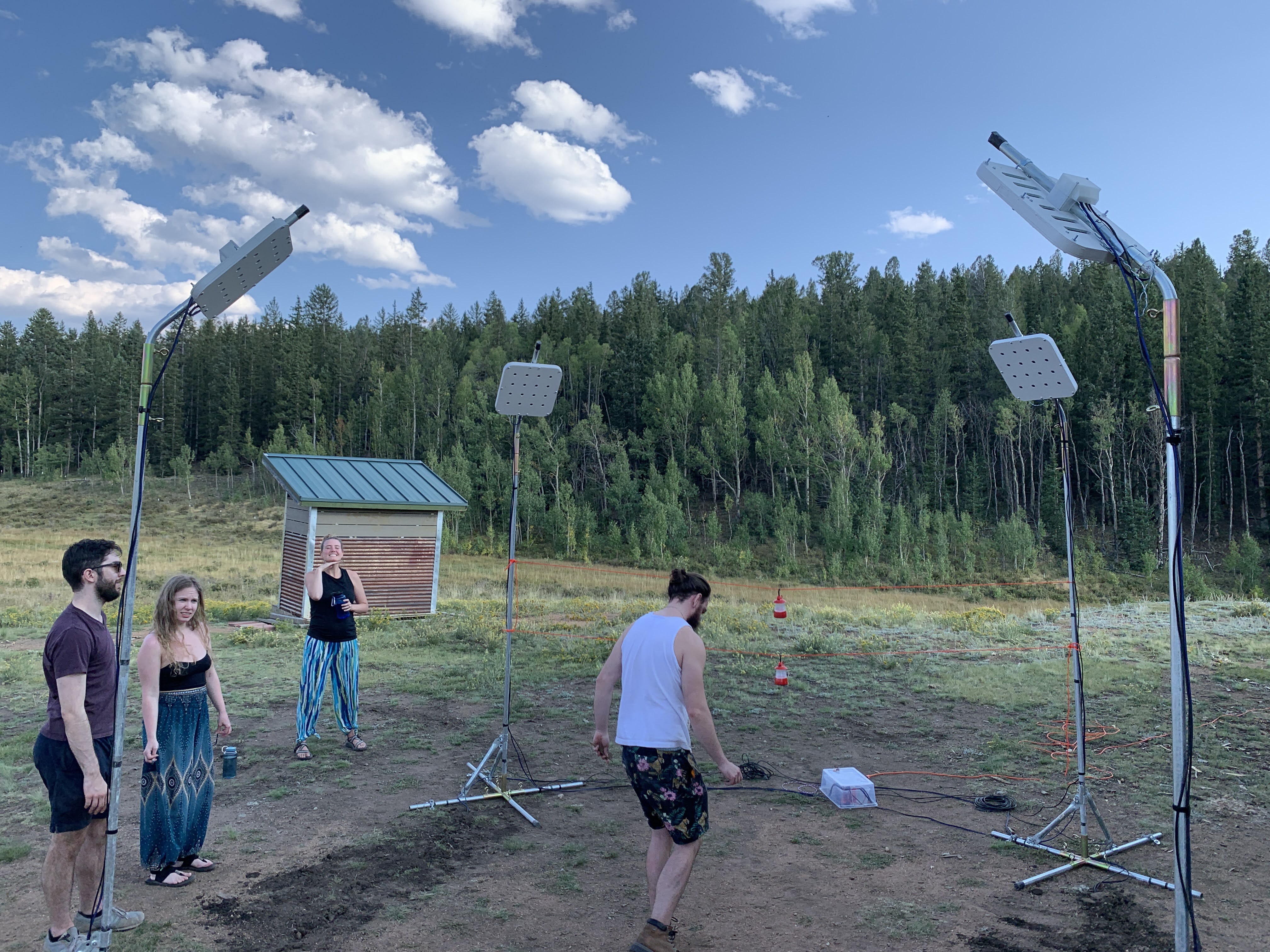
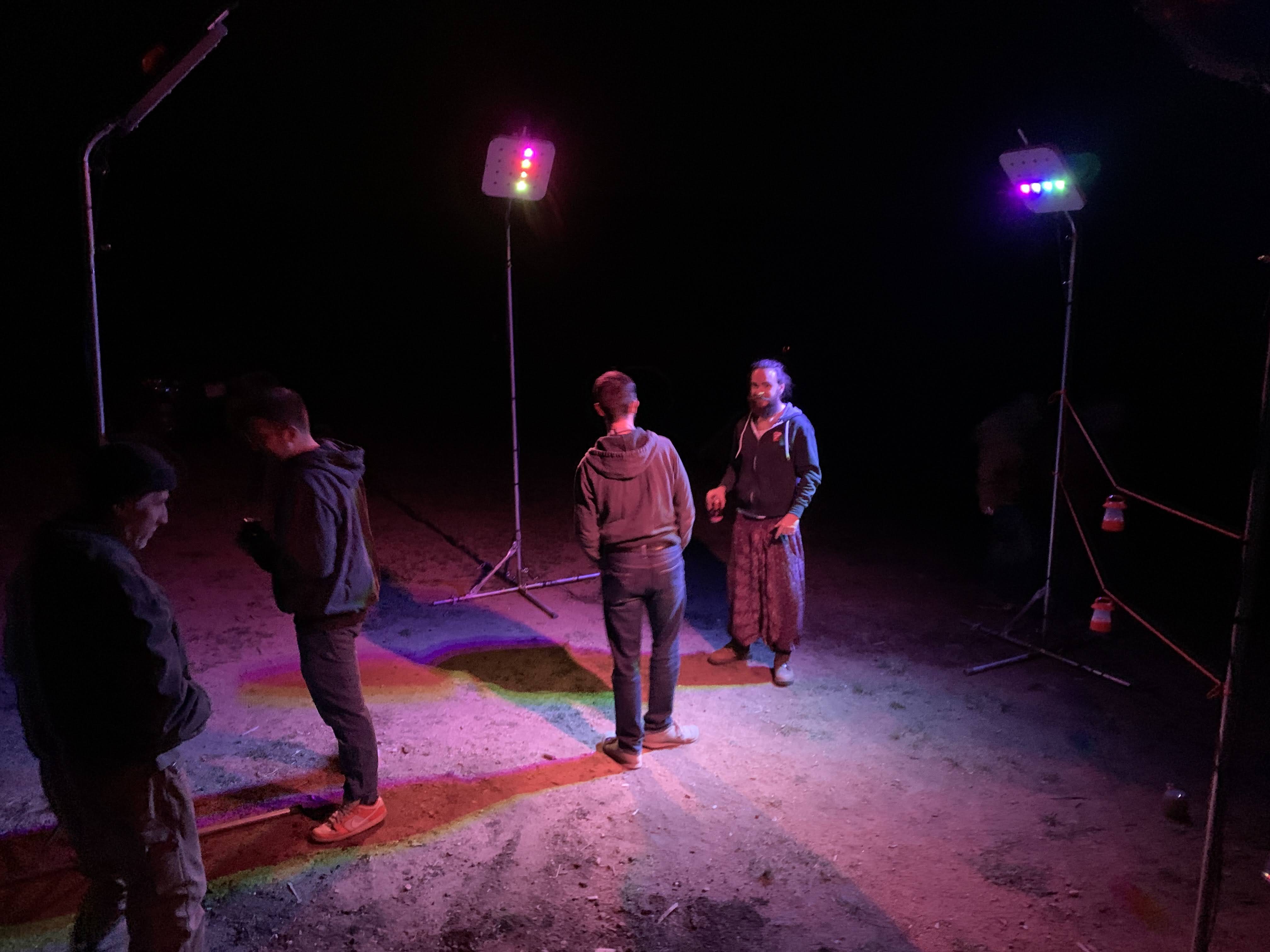
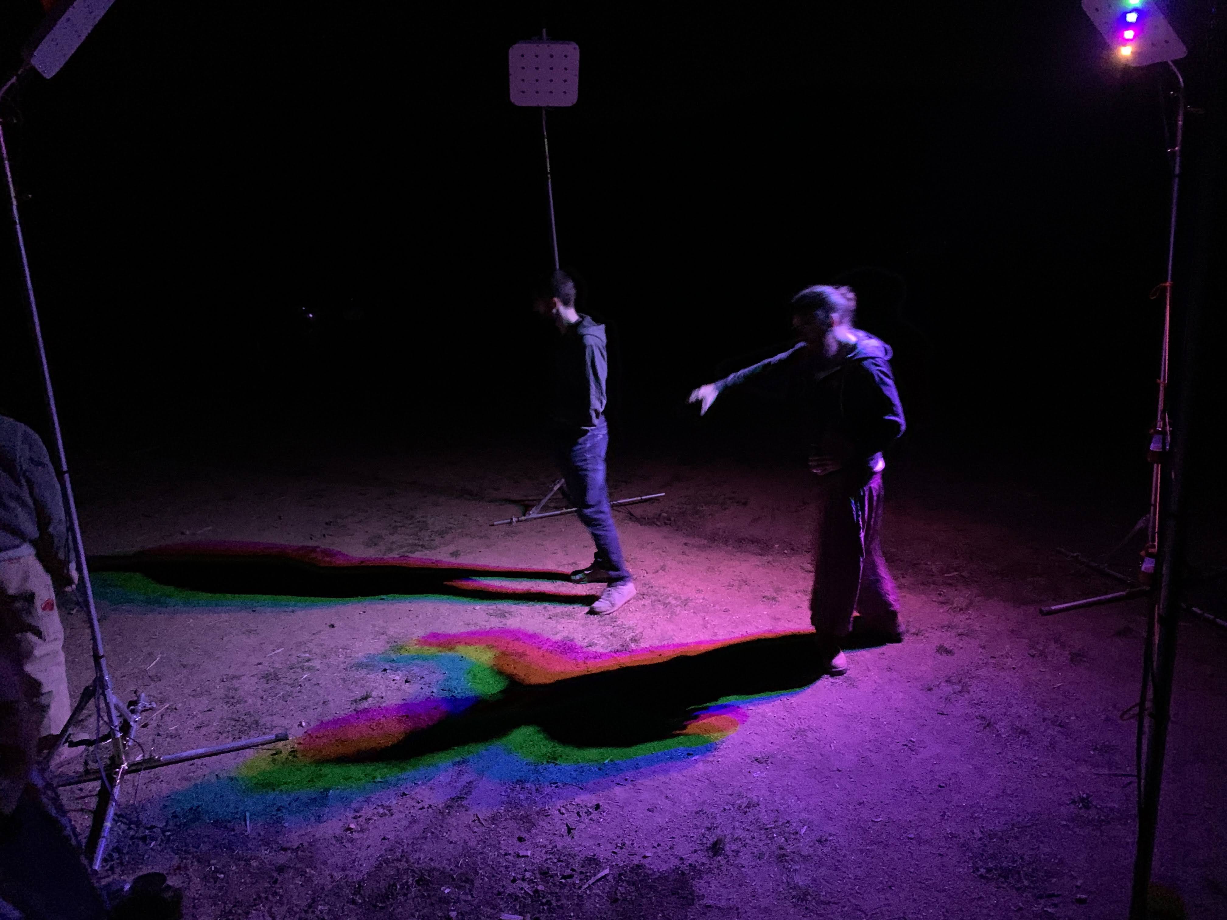
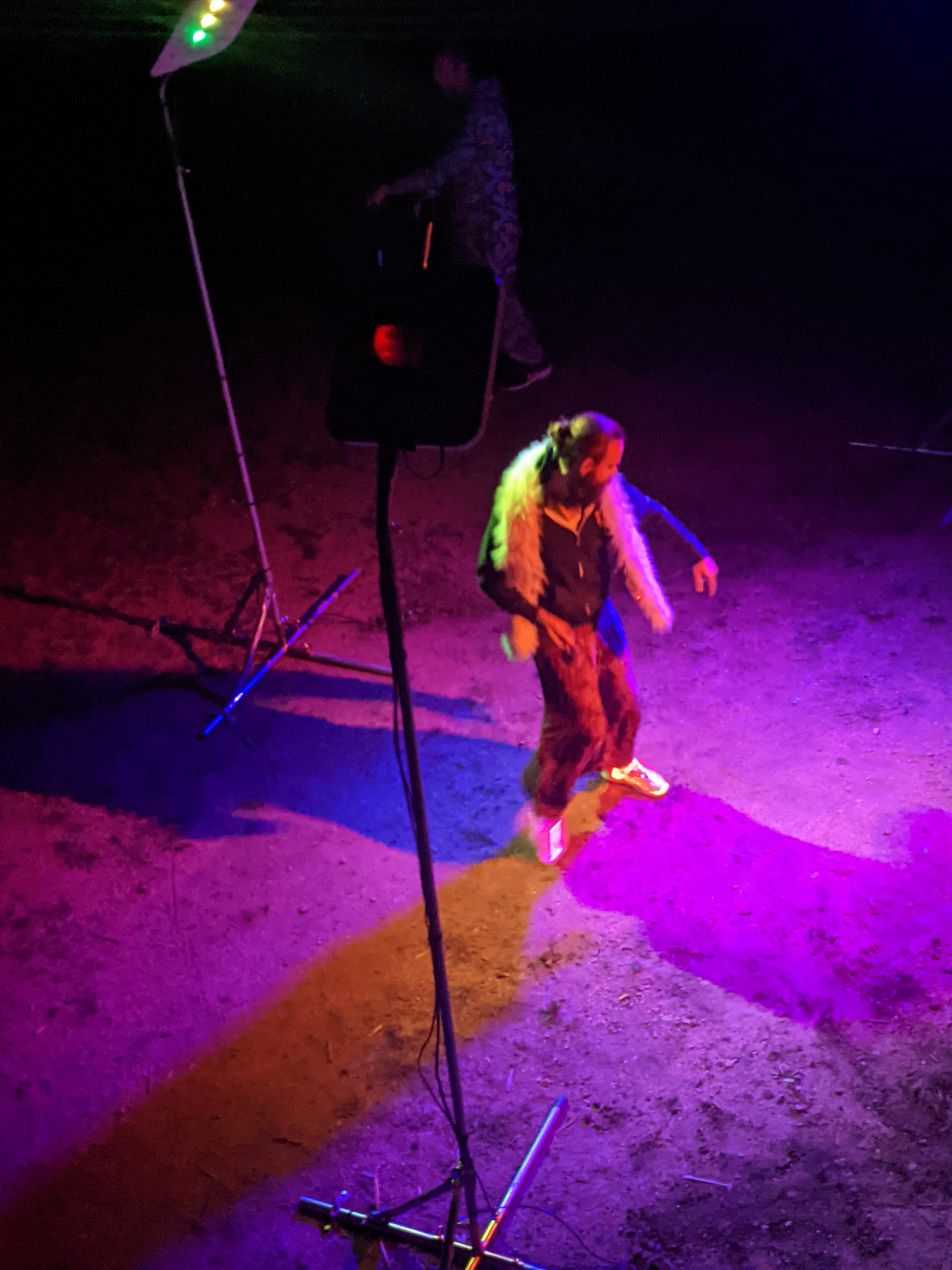
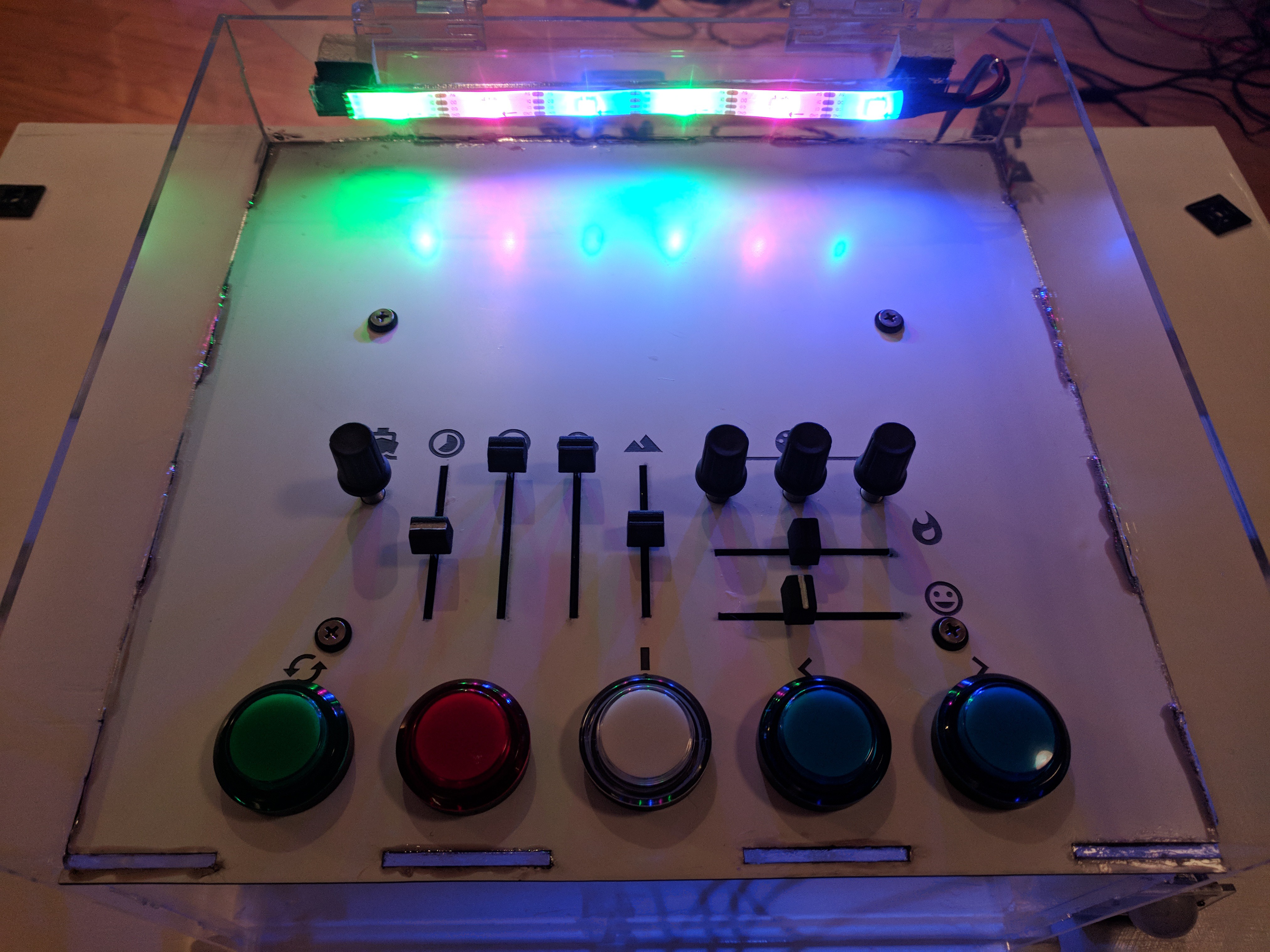
Colordance Circle
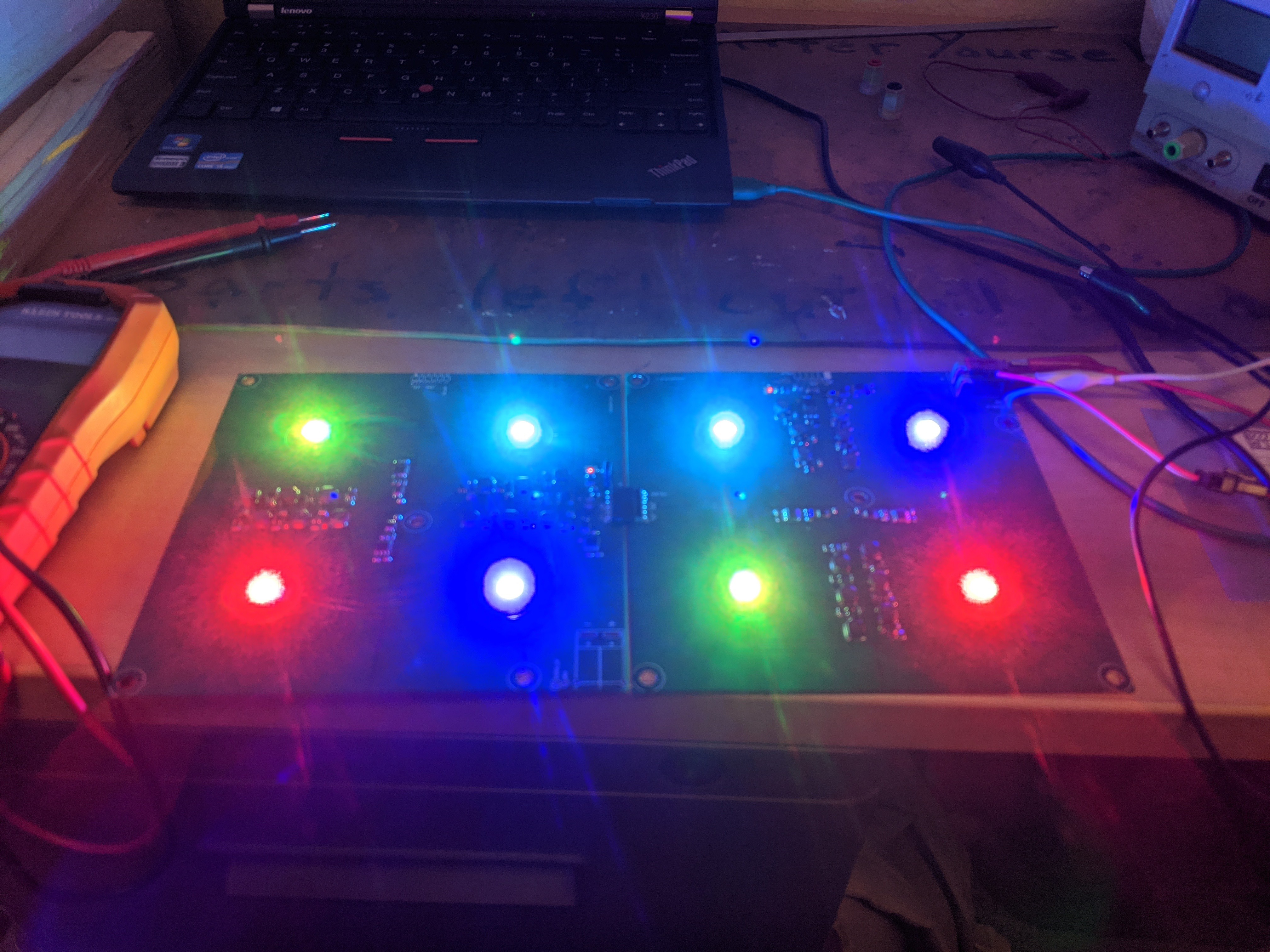
Art piece that creates kaleidoscopic colored shadows.
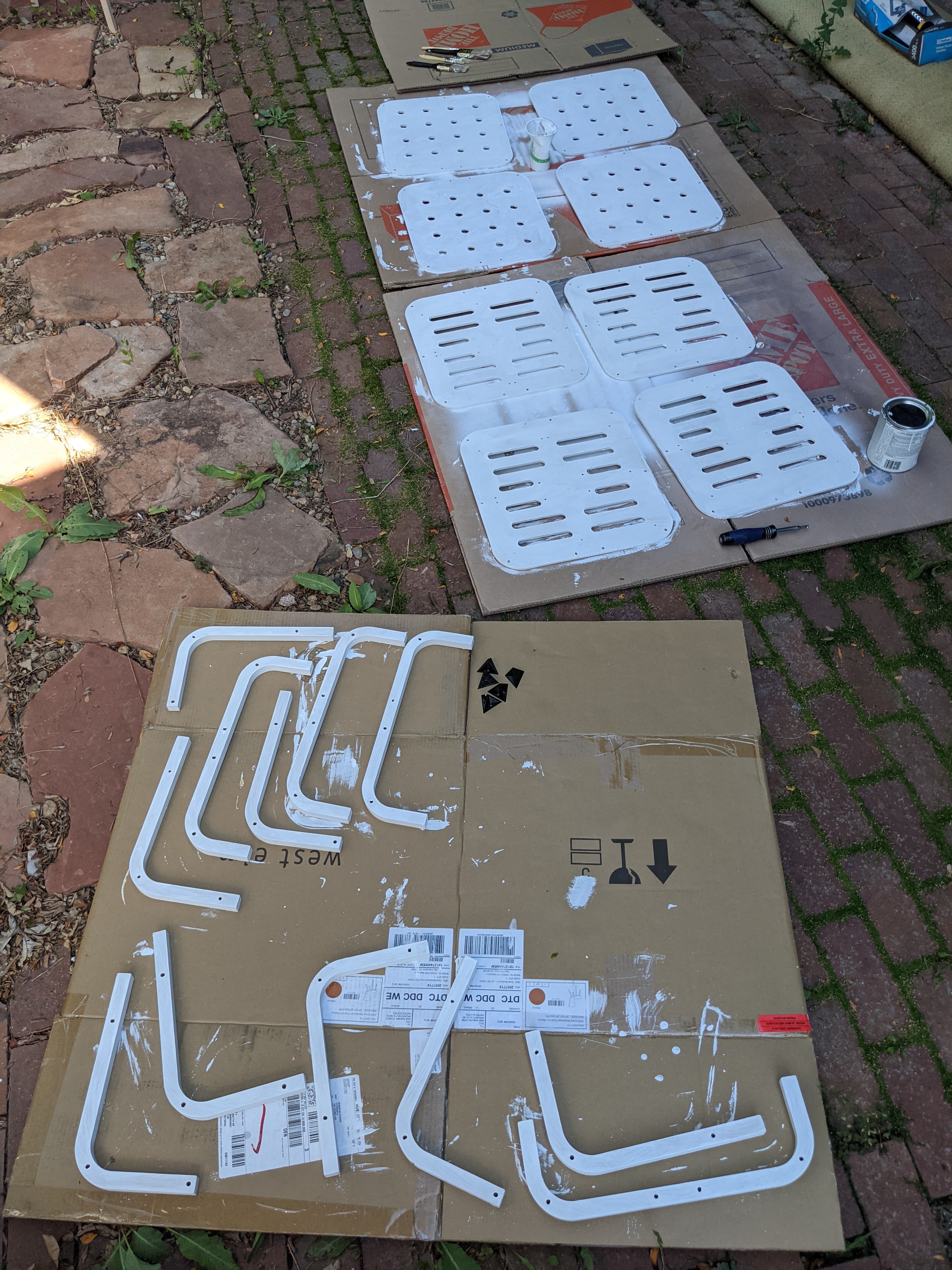
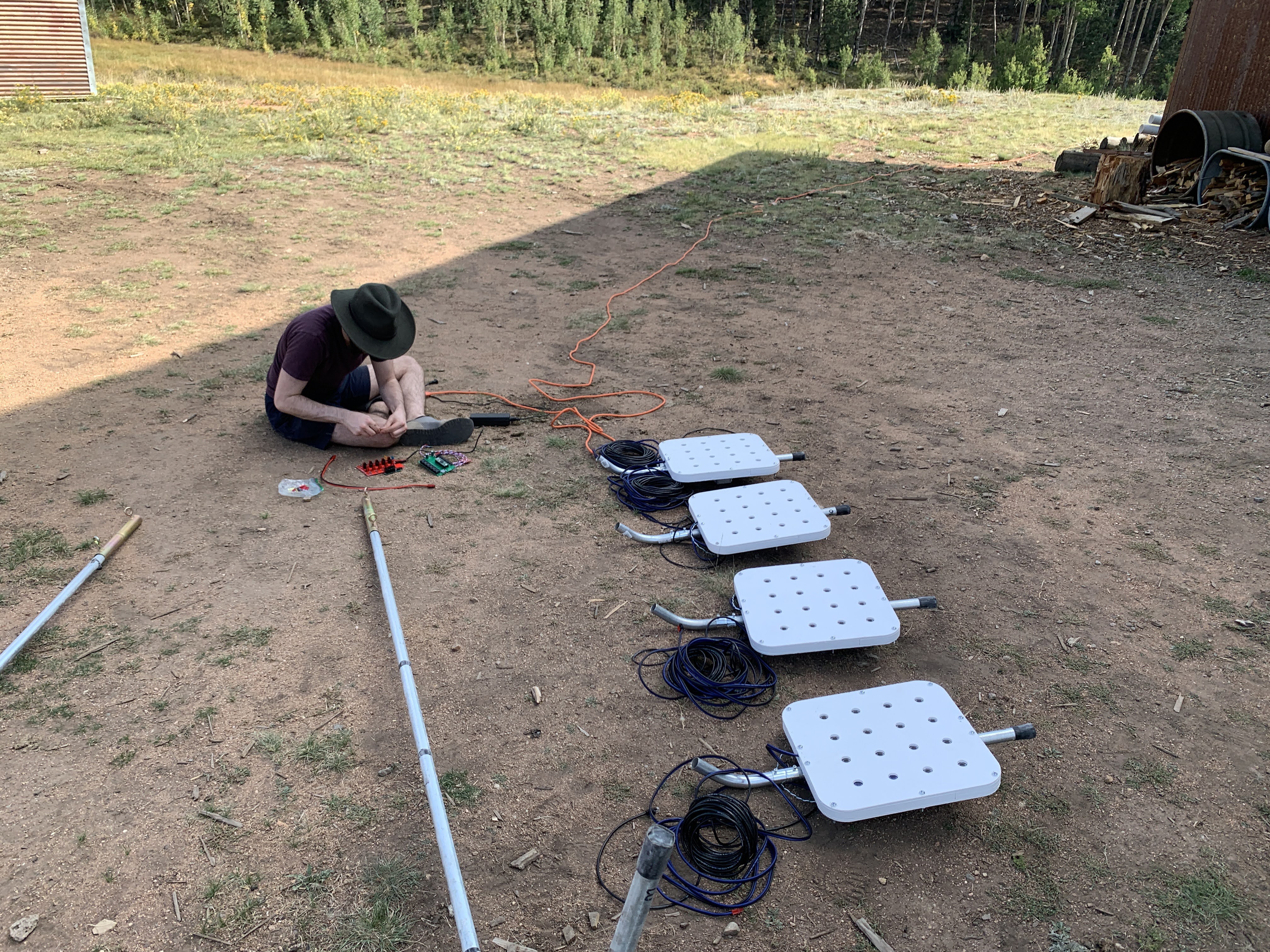
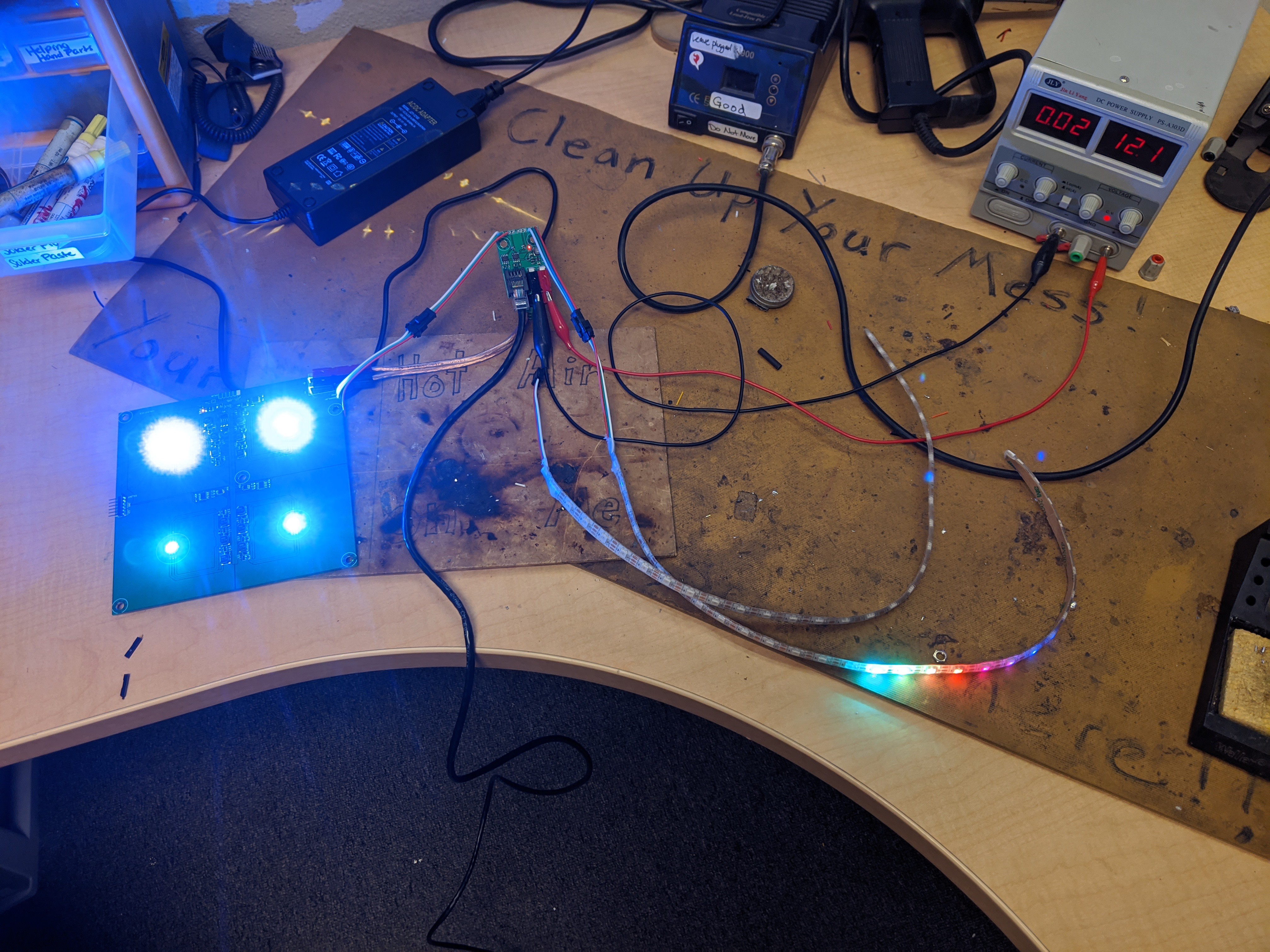
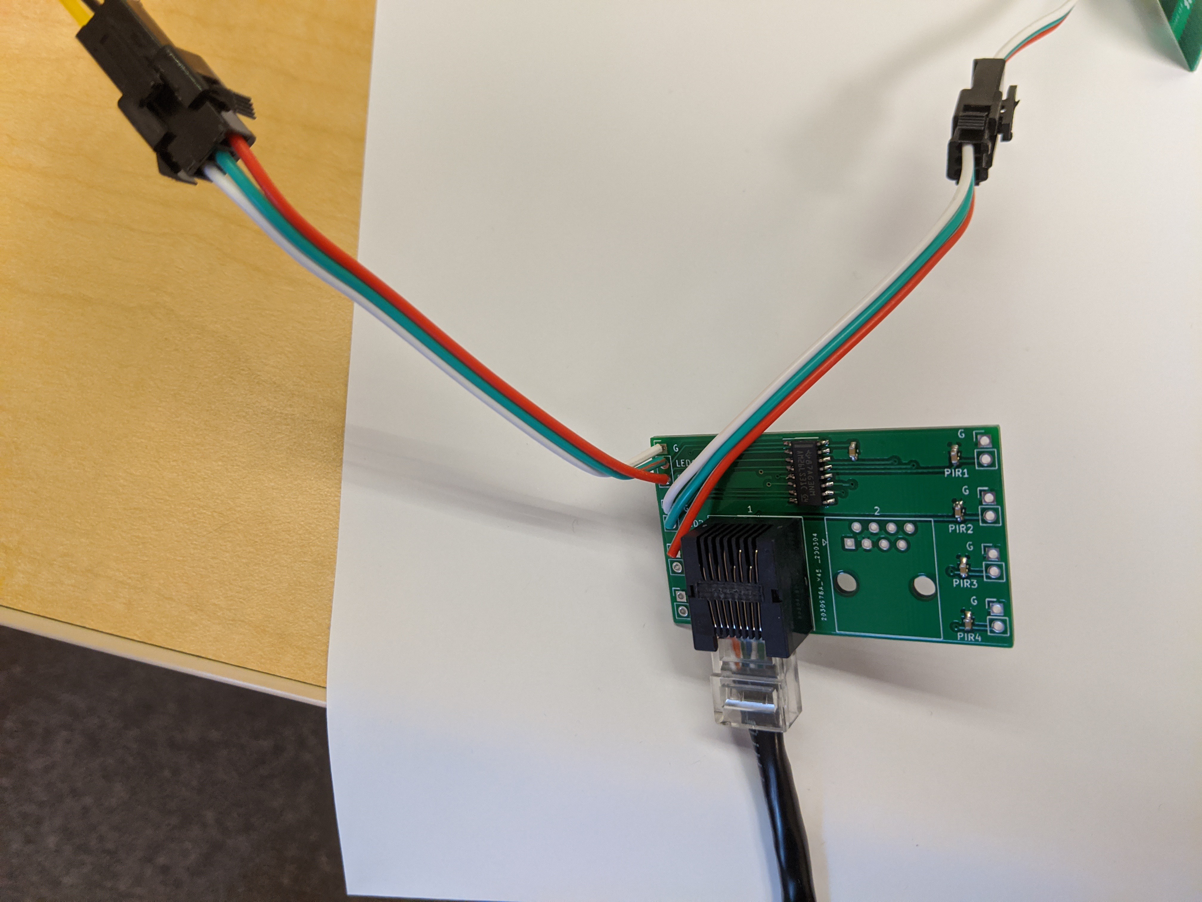
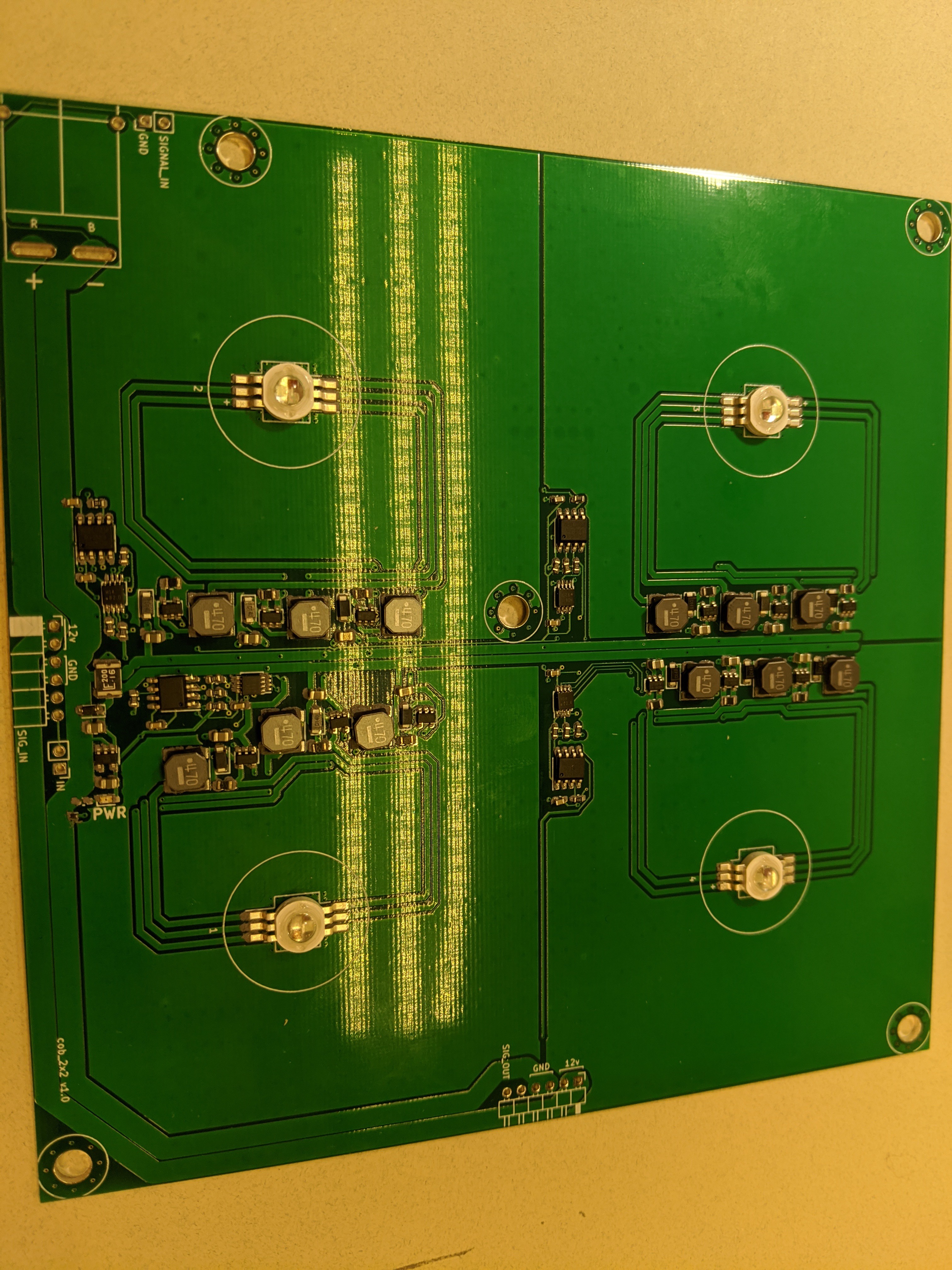
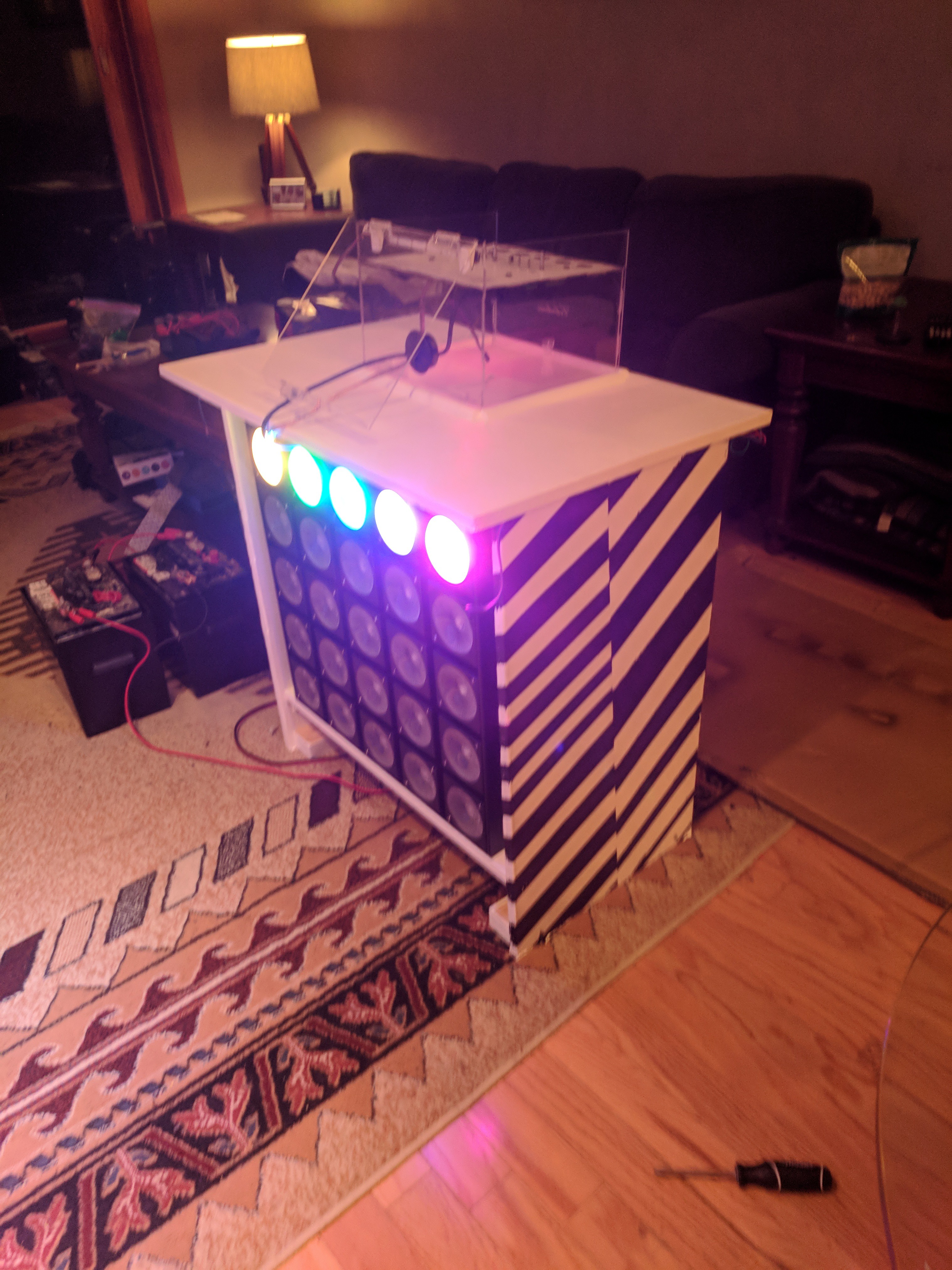
Arrays of high-powered LEDs in a circle, pointing at the center.
 Adam Demuri
Become a Hackaday.io member
Already have an account? Log in.
Just one more thing
To make the experience fit your profile, pick a username and tell us what interests you.
Pick an awesome username
hackaday.io/
Your profile's URL: hackaday.io/username. Max 25 alphanumeric characters.
Pick a few interests
Projects that share your interests
People that share your interests
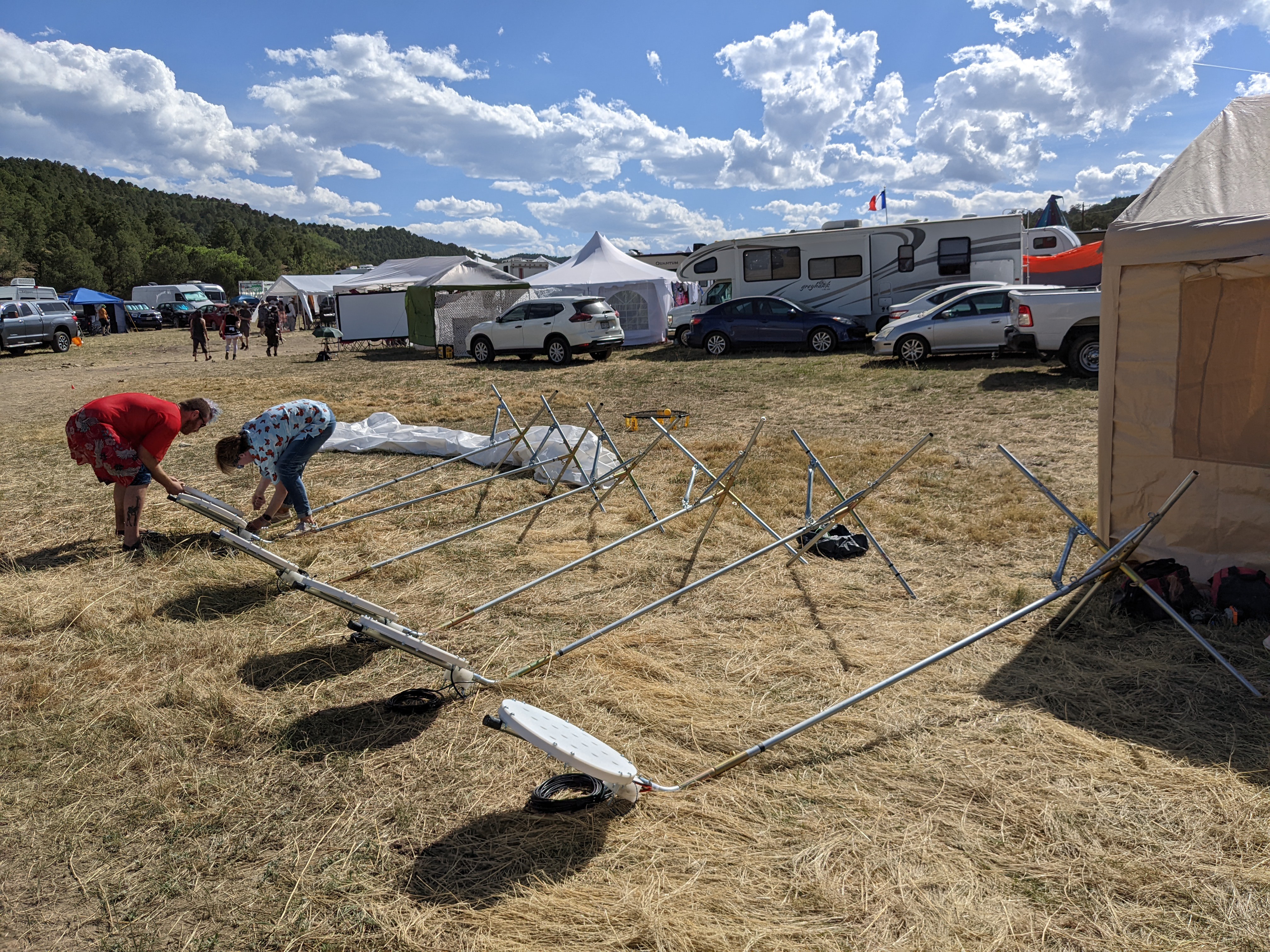
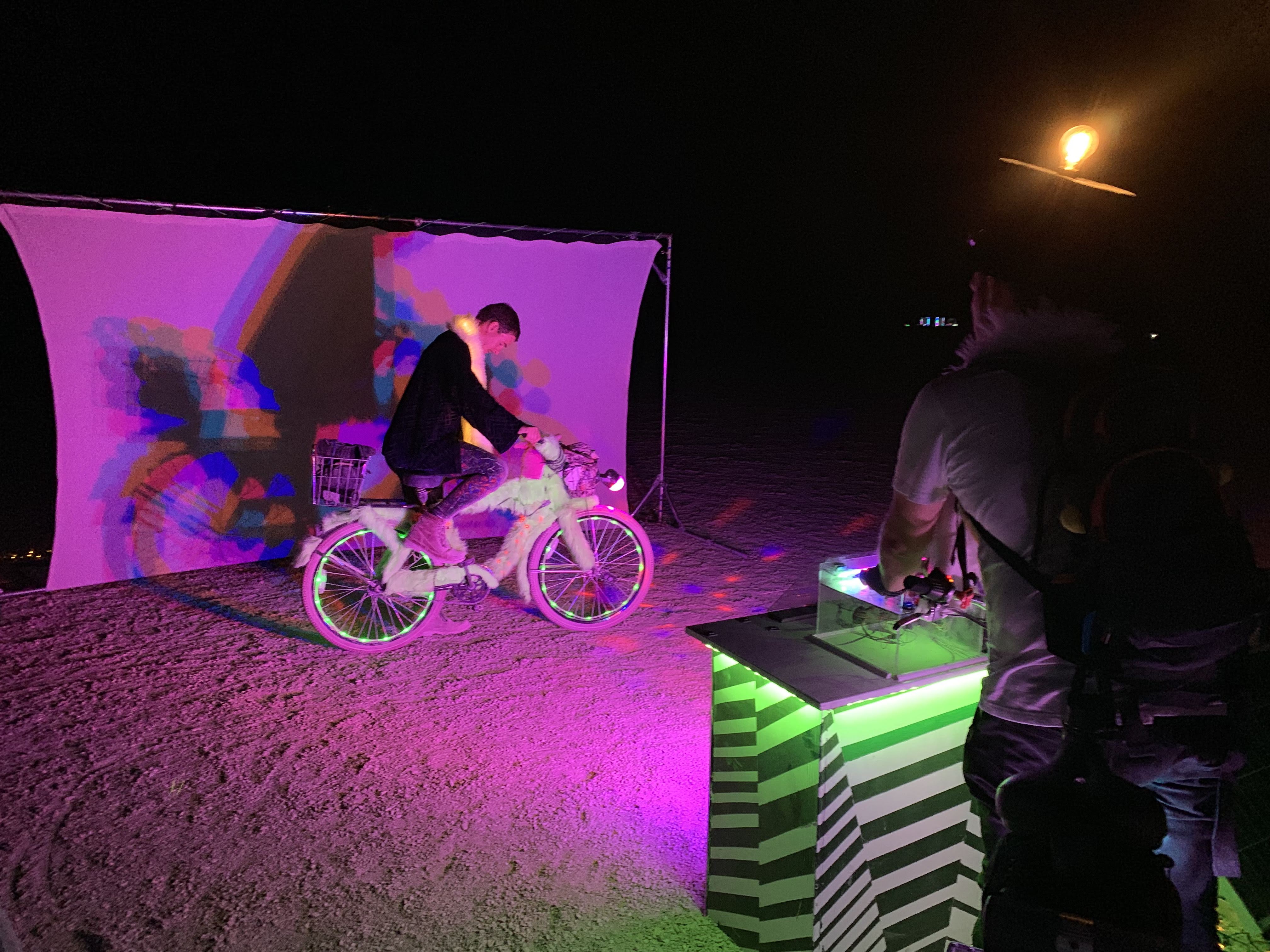
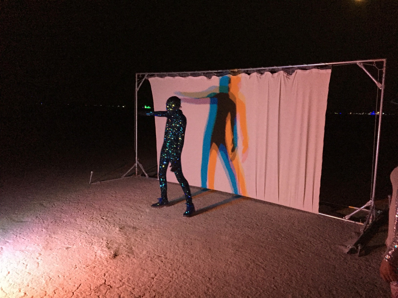
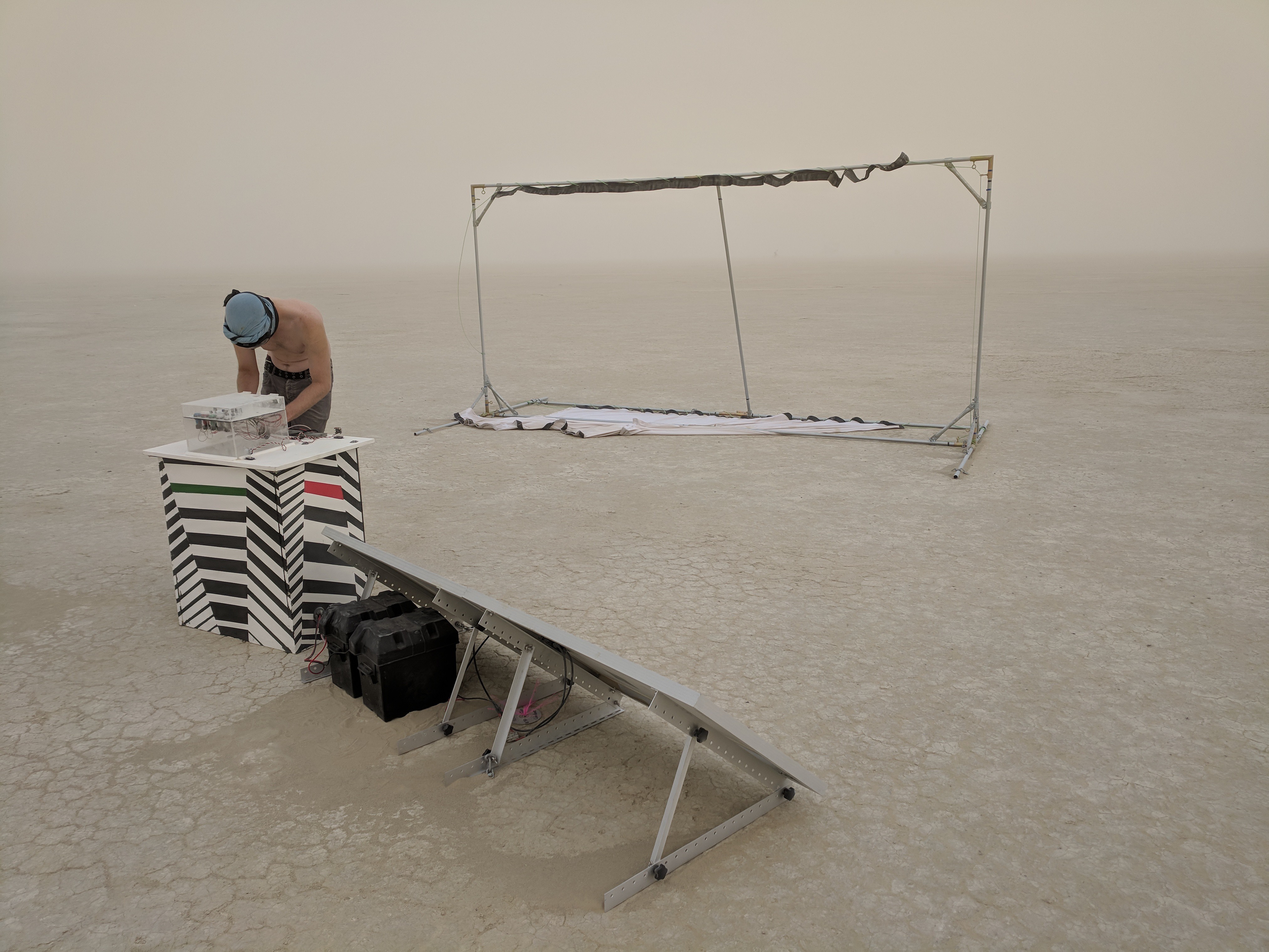 The screen is rigged on the bottom, and velcroed to a piece of rigged webbing on the top. The velcro is selectively blocked so that the screen will detach when wind speeds hit roughly 30mph.
 MughtyWinky
 Enrico
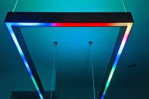
 Steve Pomeroy
 Sander van de Bor