 Michael Möller
This has been worked on for 6 months now (on-off, like all hobby projects).
The 3D design is in OpenSCAD, all parts are printed, except for a few 10x10mm profiles for the sliding servo carriage. Well, the clockface is printed on paper, too.
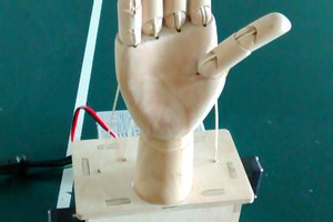
The mechnism should be obvious from the picture - one servo slides the other servo up/down to the right gear for a given clockhand. The servo then moves the hands' gear the required teeth.
Servos can only move 180 degrees, so the turning servo is lowered below the lowest gear when it needs to "rewind" before moving back to a handgear to advance it further.
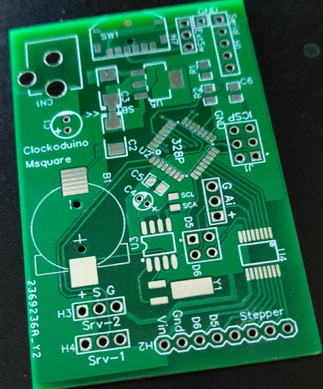
Software/electronics is a simple small Arduino, and a standard clockchip. The software uses the VarSpeedServo library to move the servos slowly to avoid breaking plastic.
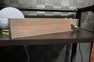
The clock face is supposed to be slightly enigmatic. The letters are calender-items, and makes it language dependent, but with seven and 12 letters in a circle, respectivly, should make it understandable anyhow. The ordering is by how many increments there are, not fastets to slowest. Lastly the hands will point exactly at a value (ie. the hour hands moves once an hour, never positioned between two hours at half past) The large drawing of the face has the hands postioned to the closing date&time of the Tell Time contest.
The clock has been shown at Makerfaires (with some fudging as the mechanism was unreliable at that time). As 3 hands only move at midnight and the hour hand only moves (obviously) once an hour it is not an eyecatching exhibit. A set of mirrors will show the innards next time, and a colour-cycling RGB has been put in there, too. A demo-mode button will let the clock show some event in the future (like the next exhibition opening), or the current time. It takes it a minute or two to move all hands to an arbitrary date/time or back to current time.


 HIGEDARUMA
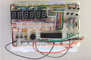
 Lilia Lobato
Will you share your SCAD file?