 Max.K
Max.K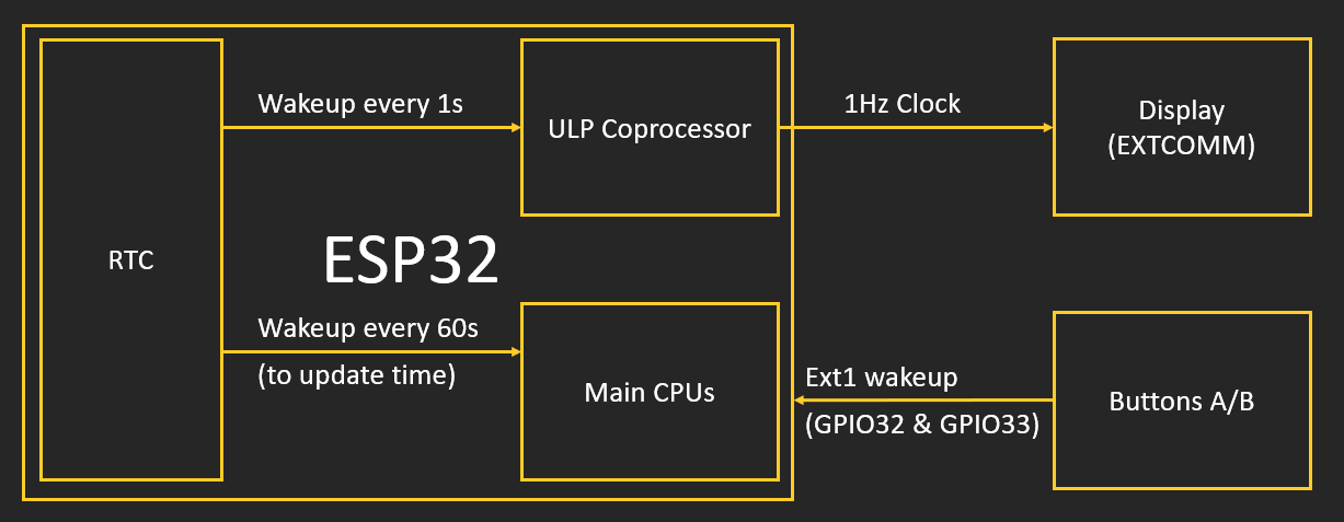
While the battery can power the handheld for only a few hours, I wanted to include a standby mode that utilizes the low power display. This way the device would be usable as a clock and calendar. There are a few things necessary to keep the display active and the battery life long. Although the memory display does not need constant refreshing over SPI, a >1Hz clock signal must be supplied to its EXTCOMM pin. Otherwise the screen shows burn-in. This means that part of the ESP32 needs to remain active during standby mode.
At 70-200mA, the ESP32 can be power-hungry with its dual cores and WiFi modem. But not everyone knows that it has some nice power saving features. In sleep mode the ESP32's main cores are powered down, reducing the current to only 10µA. During this, the internal Real Time Clock controller is still active. The RTC itself can't do much, but it can wake the ESP32's third core, the ULP coprocessor. This Ultra Low Power processor can do basic tasks like checking sensors or reading and writing pin states while only needing ~150µA. Exactly what it need for the 1Hz signal. The ULP can be woken up periodically by the RTC using:
ulp_set_wakeup_period(0, 1000 * 1000);
For the 1Hz signal the ULP coprocessor has to be programmed in assembler. Luckily Espressif has an example for a blinking LED that does exactly what I wanted:
The ESP32 can activated by different wakeup sources. For this project GPIO interrupts are needed as the device should wake up with the press of a button. The two external wakeups are ext0 and ext1. While ext0 can only be assigned to one pin, ext1 can be assigned to a map of different pins. There are a few things to consider when using the ULP core: Only the pins that can be accessed by the RTC can be used (RTC GPIO). Also I found that the internal pullup/pulldown setting are not reliable. I used hardware pulldowns for my design.
// This wakes the ESP32 with buttons on GPIO32 & GPIO33
#define BUTTON_PIN_BITMASK 0x300000000
esp_sleep_enable_ext1_wakeup(BUTTON_PIN_BITMASK,ESP_EXT1_WAKEUP_ANY_HIGH);
I want to update the time every full minute. This can't be done without waking the ESP32 for a short time:
esp_sleep_enable_timer_wakeup((60-now.tm_sec) * 1000000);
With the standby mode configured, the ES32 should only draw a few µA with short spikes when the ULP or the main cores are woken up. But there are other components on the board that need to be powered as well. The display itself draws another 10µA but also needs a 5V supply. As the LiPo battery is only at 3.7V a DC-DC converter is needed. After some searching around I found the MCP1640 from Microchip. It's a boost regulator with a quiescent current of just 19µA. The IC is small and only needs a couple of external parts. The 3.3V power supply for the ESP32 was a bigger problem. It turns out that it is hard to find a regulator with a high output current but small quiescent current, that can also be hand soldered. I ended up with the AP2112K, which can supply 600mA with a quiescent current of 55µA.
Once I had the actual PCB, testing the real power consumption was also tricky. The shunt resistance for the µA-range on most multimeters is too high to power up the ESP32. And constantly switching between ranges or swapping wires was to tedious. A user on stackexchange came up with a clever solution (https://electronics.stackexchange.com/questions/340330/measure-wide-range-of-current-800-%c2%b5a-1-5-a/340353#340353):
A diode in parallel to the multimeter will limit the voltage drop when the current is high. In sleep mode the diode barely lets current though. This way I was able to measure the power consumption in sleep mode conveniently with my 20$ multimeter.
With the ESP32 in sleep mode the current is at around 97µA. 59µA are caused by the 3.3V power supply.
These are links that I found useful:
https://www.youtube.com/watch?v=-QIcUTBB7Ww (Video about ULP programming by Andread Spiess)
https://lastminuteengineers.com/esp32-deep-sleep-wakeup-sources/
Discussions
Become a Hackaday.io Member
Create an account to leave a comment. Already have an account? Log In.
The trick is figuring out of what you lose in energy density going from LiPoly to LiFePO4 is won back by halving your standby current. As an added bonus LiFePO4 cells withstand 4x-10x as many charge/discharge cycles as LiPoly cells.
Are you sure? yes | no
You might consider using a LiFePO4 battery instead of a Lithiun Polymer battery; While the power amd energy density are somewhat lower its working voltage range of 3.6v when charging down to 3.0v when close to empty lines up rather nicely with the common specified operating range of most nominal 3.3v CMOS logic so in many cases you can use its output directly without any regulator (just some small low-leakage, low ESR tantalum caps in parallel with the battery to provide for the short load spikes of switching current).
The one gotcha is that if your SoC has an integrated battery charger it needs to be configurable enough such that you can set the maximum charge voltage to 3.60v (rather than 4.15v for LiPoly) and the discharge cutoff to 3.0v (while the LiFePO4 cells themselves _can_ operate down to 2.5v, you only give up like 3% of the energy capacity if you call 3.0v "empty" and squeezing out that last 3% shortens the cycle life significantly, and puts you past the happy zone for nominal 3.3v CMOS logic anyway).
If your charge controller can be configured for LiFePO4 it's something to think about as almost half of your standby power is going to keeping that 3.3v regulator warm.
Are you sure? yes | no
LiFePos also have a lesser tendency to explode, which is great.
Yes, all that wasted energy just for 3.3V has been bugging me. I didn't even know the ESP32 could handle 3.6V, that's very interesting. Maybe a diode would be enough to get the LiPo into the working voltage range. A LiFePo is hard to find in a pouch shape, especially in this size but I will try to find one. Thank you so much for the idea!
Are you sure? yes | no
I'm not sure the esp32 can, but most CMOS chips I've run across can (but I have encountered enough exceptions that it's worth checking).
Are you sure? yes | no
I've looked many times for small LiFePO4 cells and come up empty handed. There simply are no prismatic cells under ~5000mAh, typ. they're 10000mAh and above. So the only real small option is a 14450 (AAA size) Soshine cell, which holds 280mAh. It's a much worse form factor than the 250mAh-400mAh prismatic LiPOs.
BTW, a Ti TLV75533 regulator is good for 500mA and has an Iq of 25uA. If you're not hand soldering an NCP167 gets you 700mA and Iq of 12uA.
Q: how much does the ULP really buy you? Does it consume 150uA the whole time? It seems it takes <1ms for the esp32 to wake up from deep sleep. Toggling an I/O pin is also going to take less than 1ms. At 80Mhz the cores consume 30mA. 2ms * 30mA makes for 60uA avg, that's less than the ULP!? Plus you could clock the cores down to 10Mhz and even turn one off for this. It may be more work than using the ULP though :-). Cool use of ULP, I can never figure out what to do with it productively!
Are you sure? yes | no
@Thorsten von Eicken It's 150µA only when the ULP ist active while toggling the display pin. For the rest of the time the entire device only draws around 10µA. So it's a matter of waking up the 150µA ULP for a few ms vs. the 30mA cores.
Are you sure? yes | no